Over feeding of pipeline
The pressure drop in the conveying line is primarily dependent upon the concentration of the material in the pipeline, or the solids loading ratio. If too much material is fed into the conveying line it is possible that the pipeline could become blocked. There are two possible reasons for this. One is related to compressor delivery capability and the other is concerned with material conveying capability.
Compressor capability
If a pipeline is over fed the pressure required may exceed that available from the blower or compressor and the line will block. It will, therefore, be necessary to reduce the material feed rate to match the capability of the air mover or its drive motor. It could be either the compressor or the drive motor that imposes the limitation. The operating characteristics of the compressor and the specification of the motor could be checked to determine the exact cause of the problem. This problem relates to air mover characteristics such as those presented in Figure 6.5.
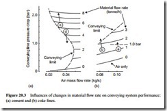
To illustrate the various problems with regard to the over feeding of a pipeline a section from each of the conveying characteristics presented in Figures 20.1 and 20.2 is re-drawn on Figure 20.3. A common axis was used for these two materials and so the air only curve could run continuously between the two sections.
Point (a) represents the coke fines successfully conveyed at 1.0 tonne/h with 0.10 kg/s of air and requiring a pressure drop of 0.8 bar. If 2 tonne/h were to be fed into the pipeline there would have to be a corresponding increase in air supply pressure because a pressure drop of about 1.1 bar would be needed. If a positive displacement blower was used to supply the air, having a maximum pressure capability of 1.0 bar gauge, it is quite possible that the new operating point could not be reached and the pipeline would block.
Point (b) represents the coke also being conveyed with a pressure drop of 0.8 bar. With a lower air flow rate a slightly higher material flow rate is achieved. The conveying air velocity is 20 per cent above the minimum at this operating point and the material conveys quite successfully. If the material flow rate is increased a corresponding increase in pressure drop will be required to meet the demand. In this case the pipeline will block, even if the air mover is capable of providing the air at a higher pressure, because the operating point has crossed the conveying limit into the ‘no go area’. This can be explained by reference to Equation (20.2). The air supply pressure, p1, is on the bottom line of the equation and so as its value increases, the value of the conveying line inlet air velocity, C1, will reduce and when the value drops below the minimum for the
material the pipeline will block. An air mover with a higher air flow rate capability would be needed to recover the situation.
It will be noticed that there is a slight reduction in the air flow rate as the pressure increases for points (a) and (b) on Figure 20.3. This is a consequence of the constant speed operating characteristics of the air mover, as considered with Figures 6.3 and 6.5. With the air flow rate being on the top line of Equation (20.2) this does aggravate the situation and mean that the conveying air velocity reduces very quickly. If it is known that there are likely to be times when surges in material flow rate are likely to occur, or that a slightly higher material flow rate will be required occasionally, then a margin much greater than 20 per cent must be built into the design specification.
Material capability
With a material such as cement the same situation will apply but with dense phase conveying at low velocity the lines of constant conveying line inlet air velocity, and hence the conveying limit itself, are very much steeper, as shown on Figure 16.1 for the cement. In the transition region between dilute and dense phase conveying, however, the situation is rather different, as will be seen from operating point (c) on Figure 20.3. An increase in material flow rate here will result in an increase in solids loading ratio and this in turn will result in a lowering of the conveying limit, as shown on Figure 16.5. As a consequence the new operating point is likely to be more than 20 per cent above the conveying limit, despite the slight reduction in air flow rate delivered by the compressor.
Point (d) on Figure 20.3 illustrates the reverse situation. This is pipeline blockage as a consequence of reducing the material flow rate, which can only occur with dense phase conveying. In the transition region between fully dense phase conveying and dilute phase conveying there is a switch from a minimum conveying air velocity of about 11 m/s, for the dilute phase conveying of this type of material, to a minimum conveying air velocity of about 3 m/s. It is in this region that such problems can occur. This was illustrated in detail with Figure 13.5 which shows the relationship between minimum conveying air velocity and solids loading ratio, and Figure 13.6 which shows the specific area on the conveying characteristics to a magnified scale. A reduction in material flow rate from point (d) will reduce the solids loading ratio which in turn will raise the value of conveying air velocity and the pipeline could block as a result.
Feeder control
Each type of pipeline feeding device has its own characteristic means of controlling the material flow. With positive displacement feeders this is achieved directly: either by means of speed control, as in the case of rotary valves and screws; or by frequency of operation, as in the case of double gate valves. In others, additional flow control devices are required, as with venturi feeders. In the case of blow tanks and suction nozzles, control is achieved by means of air supply proportioning.
Feed control is very important at the time of commissioning a plant, particularly with conveying systems employing positive displacement feeders. Due to the expense, these feeders are not generally supplied with a variable speed drive, unless there is a particular requirement during operation of the plant to be able to vary the feed rate. With rotary valves, for example, there is often a problem with achieving fine control of feed rate, since a change of just 1 or 2 rev/min can have a significant effect on material flow rate. On commissioning, therefore, it is essential that a means of obtaining a reasonable degree of speed control should be provided, either side of the estimated value, so that fine control of the flow rate can be achieved.
Performance monitoring
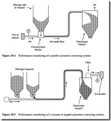
It is often difficult to assess whether a pipeline blockage results from an incorrect air mover specification, or over feeding of the pipeline. For a positive pressure system this can be established quite easily if there is a pressure gauge in the air supply line just before the material feed point into the conveying line. A typical arrangement is shown in Figure 20.4.
In a negative pressure, or vacuum conveying system, the pressure gauge would have to be located in the discharge air pipeline between the filtration unit and the inlet to the exhauster, as shown in Figure 20.5. Such a pressure gauge, in either the positive or negative pressure system, will give a reasonably close approximation to the con- veying line pressure drop, for the pressure drop in the short section of the air supply line will be small in comparison. The pressure gauge will also work more reliably in the air line than it will in the material conveying line.
Note: Many of the comments that follow refer only to positive pressure conveying systems, but are equally applicable to negative pressure systems. This is simply to avoid making the text unnecessarily complicated in referring to two different cases at every juncture. The main difference between positive and negative pressure conveying systems is in the specification of the volumetric flow rate of the air, since that for exhausters is generally in terms of exhauster inlet conditions.
If the reading on the pressure gauge is above the design value it would indicate that the pipeline is being over fed, and so the feed rate should be reduced. If the pressure is at the design value or below, and the pipeline blocks, it would indicate that the volumetric flow rate is insufficient. Pipeline blockage can occur very rapidly, particularly with high velocity dilute phase conveying. In a 100 m long pipeline, for example, with a mean conveying air velocity of 20 m/s the air will traverse the pipeline in 5 s. The particles are conveyed at a slightly lower velocity but they will only take a few seconds longer.
A pressure gauge in the air line is particularly useful for monitoring the performance of a system. If the pressure reading is below the design value, for example, it would indicate that the performance of the system has been under estimated and that it would be possible to feed more material into the pipeline. Care must be exercised here, how- ever, and the air velocities should be checked as mentioned above, for an increase in air supply pressure will result in a lowering of the conveying line inlet air velocity.
The use of pressure gauges, such as those shown on Figures 20.4 and 20.5 would also be invaluable in achieving the correct balance between material feed rate, and air supply pressure and flow rate, if a change in either conveying distance or a change in material conveyed were to be made.
Influence of pressure
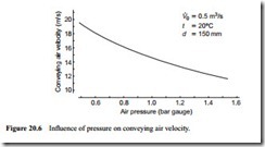
The influence of pressure, as it is such an important parameter, is illustrated further in Figure 20.6. This is a graph of conveying air velocity plotted against a narrow band of air pressure. It is derived from Equation (20.2), for a free air flow rate of 0.5 m3/s at 20°C in a 150 mm bore pipeline. It should also be noted that with most positive displacement air movers there is a slight reduction in volumetric flow rate with increase in delivery pressure, as illustrated on Figure 20.3, and this will magnify the effect.
Figure 20.6 is drawn on a magnified scale and shows quite clearly the very significant effect that changes in pressure can have on conveying air velocity. Some fine granular materials, such as sand, sugar and alumina, are very sensitive to small changes in con- veying air velocity.
Silica sand, for example, will convey very reliably with a conveying line inlet air velocity of 14 m/s, but if it drops to only 13.6 m/s the pipeline will block within seconds. Granulated sugar, having a mean particle size of about 460 1Jm, is a similar material that will convey reliably with a conveying line inlet air velocity of 16.2 m/s but will rapidly block the pipeline if the velocity falls to 15.8 m/s. It only requires a small change in air supply pressure, for a given air flow rate, to result in this change in conveying air velocity.


