Pressure regulation
Flow velocities in pneumatic systems can be quite high, which can lead to significant flow-dependent pressure drops between the air receiver and the load.
Generally, therefore, air pressure in the receiver is set higher than the required load pressure and pressure regulation is performed local to loads to keep pressure constant regardless of flow. Control of air pressure in the receiver was described in an earlier section. This section describes various ways in which pressure is locally controlled.
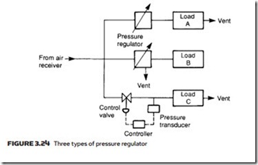
There are essentially three methods of local pressure control, illustrated in Figure 3.24. Load A vents continuously to atmosphere. Air pressure is controlled by a pressure regulator which simply restricts air flow to the load. This type of regulator requires some minimum flow to operate. If used with a dead-end load which draws no air, the air pressure will rise to the main manifold pressure. Such regulators, in which air must pass through the load, are called non-relieving regulators.
Load B is a dead-end load, and uses a pressure regulator which vents air to atmosphere to reduce pressure. This type of regulator is called a three-port (for
the three connections) or relieving regulator. Finally, load C is a large-capacity load whose air volume requirements are beyond the capacity of a simple in-line regulator. Here a pressure control loop has been constructed comprising pres- sure transducer, electronic controller and separate vent valve. This technique can also be used if the pressure-regulating valve cannot be mounted locally to the point at which the pressure is to be controlled.

