MECHANICAL FORMS OF WORK
There are several different ways of doing work, each in some way related to a force acting through a distance (Fig. 4–16). In elementary mechanics, the work done by a constant force F on a body displaced a distance s in the direction of the force is given by
Obviously one needs to know how the force varies with displacement to per- form this integration. Equations 4–8 and 4–9 give only the magnitude of the work. The sign is easily determined from physical considerations: The work done on a system by an external force acting in the direction of motion is negative, and work done by a system against an external force acting in the opposite direction to motion is positive.
There are two requirements for a work interaction between a system and its surroundings to exist: (1) there must be a force acting on the boundary, and (2) the boundary must move. Therefore, the presence of forces on the bound- ary without any displacement of the boundary does not constitute a work interaction. Likewise, the displacement of the boundary without any force to oppose or drive this motion (such as the expansion of a gas into an evacuated space) is not a work interaction since no energy is transferred.
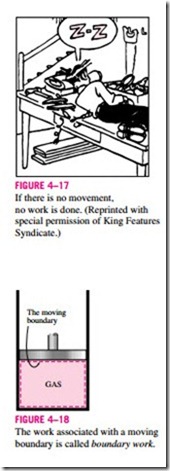
In many thermodynamic problems, mechanical work is the only form of work involved. It is associated with the movement of the boundary of a sys- tem or with the movement of the entire system as a whole (Fig. 4–17). Some common forms of mechanical work are discussed next.
1 Moving Boundary Work
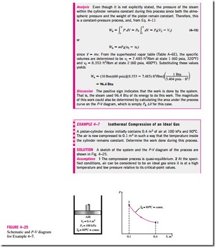
One form of mechanical work frequently encountered in practice is associated with the expansion or compression of a gas in a piston-cylinder device. During this process, part of the boundary (the inner face of the piston) moves back and forth. Therefore, the expansion and compression work is often called moving boundary work, or simply boundary work (Fig. 4–18). Some call it the P dV work for reasons explained later. Moving boundary work is the primary form of work involved in automobile engines. During their expansion, the combustion gases force the piston to move, which in turn forces the crank- shaft to rotate.
The moving boundary work associated with real engines or compressors cannot be determined exactly from a thermodynamic analysis alone because the piston usually moves at very high speeds, making it difficult for the gas in- side to maintain equilibrium. Then the states through which the system passes during the process cannot be specified, and no process path can be drawn. Work, being a path function, cannot be determined analytically without a knowledge of the path. Therefore, the boundary work in real engines or compressors is determined by direct measurements.
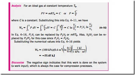
In this section, we analyze the moving boundary work for a quasi- equilibrium process, a process during which the system remains in equilibrium at all times. A quasi-equilibrium process, also called a quasi-static process, is closely approximated by real engines, especially when the piston moves at low velocities. Under identical conditions, the work output of the engines is found to be a maximum, and the work input to the compressors to be a minimum when quasi-equilibrium processes are used in place of nonquasi- equilibrium processes. Below, the work associated with a moving boundary is evaluated for a quasi-equilibrium process.
Consider the gas enclosed
in the piston-cylinder device shown in Fig. 4–19. The initial pressure of the gas is P, the total volume is V, and the cross- sectional area of the piston is A. If the piston is allowed to move a distance ds in a quasi-equilibrium manner, the differential work done during this process is
That is, the boundary work in the differential form is equal to the product of the absolute pressure P and the differential change in the volume dV of the system. This expression also explains why the moving boundary work is sometimes called the P dV work.
Note in Eq. 4–10 that P is the absolute pressure, which is always positive. However, the volume change dV is positive during an expansion process (volume increasing) and negative during a compression process (volume decreasing). Thus, the boundary work is positive during an expansion process and negative during a compression process. Therefore, Eq. 4–10 can be viewed as an expression for boundary work output, Wb, out. A negative result indicates boundary work input (compression).
The total boundary work done during the entire process as the piston moves is obtained by adding all the differential works from the initial state to the final state:
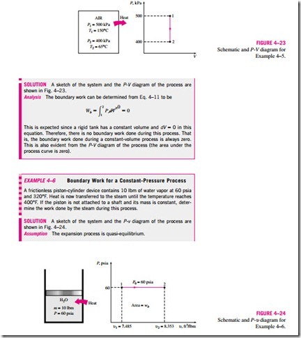
This integral can be evaluated only if we know the functional relationship be- tween P and V during the process. That is, P = f (V) should be available. Note that P = f (V) is simply the equation of the process path on a P–V diagram. The quasi-equilibrium expansion process described above is shown on a P–V diagram in Fig. 4–20. On this diagram, the differential area dA is equal to P dV, which is the differential work. The total area A under the process curve 1–2 is obtained by adding these differential areas:
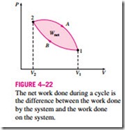
A comparison of this equation with Eq. 4–11 reveals that the area under the process curve on a P-V diagram is equal, in magnitude, to the work done during a quasi-equilibrium expansion or compression process of a closed system. (On the P-u diagram, it represents the boundary work done per unit mass.) A gas can follow several different paths as it expands from state 1 to state 2. In general, each path will have a different area underneath it, and since this area represents the magnitude of the work, the work done will be different for each process (Fig. 4–21). This is expected, since work is a path function (i.e., it depends on the path followed as well as the end states). If work were not a path function, no cyclic devices (car engines, power plants) could operate as work-producing devices. The work produced by these devices during one part of the cycle would have to be consumed during another part, and there would be no net work output. The cycle shown in Fig. 4–22 produces a net work out- put because the work done by the system during the expansion process (area under path A) is greater than the work done on the system during the compression part of the cycle (area under path B), and the difference between these two is the net work done during the cycle (the colored area).
If the relationship between P and V during an expansion or a compression process is given in terms of experimental data instead of in a functional form, obviously we cannot perform the integration analytically. But we can always plot the P–V diagram of the process, using these data points, and calculate the area underneath graphically to determine the work done.
Strictly speaking, the pressure P in Eq. 4–11 is the pressure at the inner surface of the piston. It becomes equal to the pressure of the gas in the cylinder only if the process is quasi-equilibrium and thus the entire gas in the cylinder is at the same pressure at any given time. Equation 4–11 can also be used for nonquasi-equilibrium processes provided that the pressure at the inner face of the piston is used for P. (Besides, we cannot speak of the pressure of a system during a nonquasi-equilibrium process since properties are defined for equilibrium states.) Therefore, we can generalize the boundary work relation by expressing it as
where Pi is the pressure at the inner face of the piston.
Note that work is a mechanism for energy interaction between a system and its surroundings, and Wb represents the amount of energy transferred from the system during an expansion process (or to the system during a compression process). Therefore, it has to appear somewhere else and we must be able to account for it since energy is conserved. In a car engine, for example, the boundary work done by the expanding hot gases is used to overcome friction between the piston and the cylinder, to push atmospheric air out of the way, and to rotate the crankshaft. Therefore,
Of course the work used to overcome friction will appear as frictional heat and the energy transmitted through the crankshaft will be transmitted to other components (such as the wheels) to perform certain functions. But note that the energy transferred by the system as work must equal the energy received by the crankshaft, the atmosphere, and the energy used to overcome friction. The use of the boundary work relation is not limited to the quasi- equilibrium processes of gases only. It can also be used for solids and liquids.
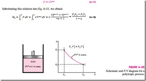
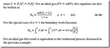
Polytropic Process
During actual expansion and compression processes of gases, pressure and volume are often related by PVn = C, where n and C are constants. A process of this kind is called a polytropic process (Fig. 4–26). Below we develop a general expression for the work done during a polytropic process. The pressure for a polytropic process can be expressed as
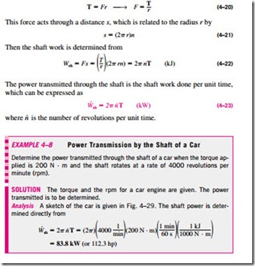
2 Shaft Work
Energy transmission with a rotating shaft is very common in engineering practice (Fig. 4–27). Often the torque T applied to the shaft is constant, which means that the force F applied is also constant. For a specified constant torque, the work done during n revolutions is determined as follows: A force F acting through a moment arm r generates a torque T of (Fig. 4–28)
3 Spring Work
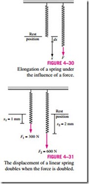
It is common knowledge that when a force is applied on a spring, the length of the spring changes (Fig. 4–30). When the length of the spring changes by a differential amount dx under the influence of a force F, the work done is
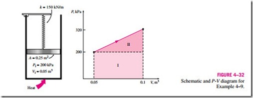
To determine the total spring work, we need to know a functional relationship between F and x. For linear elastic springs, the displacement x is proportional to the force applied (Fig. 4–31). That is,
where k is the spring constant and has the unit kN/m. The displacement x is measured from the undisturbed position of the spring (that is, x = 0 when F = 0). Substituting Eq. 4–25 into Eq. 4–24 and integrating yield
where x1 and x2 are the initial and the final displacements of the spring, respectively, measured from the undisturbed position of the spring.
4 Other Mechanical Forms of Work
There are many other forms of mechanical work. Next we introduce some of them briefly.
Work Done on Elastic Solid Bars
Solids are often modeled as linear springs because under the action of a force they contract or elongate, as shown in Fig. 4–33, and when the force is lifted, they return to their original lengths, like a spring. This is true as long as the force is in the elastic range, that is, not large enough to cause permanent (plastic) deformations. Therefore, the equations given for a linear spring can also be used for elastic solid bars. Alternately, we can determine the work associated with the expansion or contraction of an elastic solid bar by replacing pressure P by its counterpart in solids, normal stress sn = F/A, in the bound- ary work expression:
where A is the cross-sectional area of the bar. Note that the normal stress has pressure units.
Work Associated with the Stretching of a Liquid Film
Consider a liquid film such as soap film suspended on a wire frame (Fig. 4–34). We know from experience that it will take some force to stretch this film by the movable portion of the wire frame. This force is used to overcome the microscopic forces between molecules at the liquid–air interfaces. These microscopic forces are perpendicular to any line in the surface, and the force generated by these forces per unit length is called the surface tension ss, whose unit is N/m. Therefore, the work associated with the stretching of a film is also called surface tension work. It is determined from
where dA = 2b dx is the change in the surface area of the film. The factor 2 is due to the fact that the film has two surfaces in contact with air. The force act- ing on the movable wire as a result of surface tension effects is F = 2bss where ss is the surface tension force per unit length.
Work Done to Raise or to Accelerate a Body
When a body is raised in a gravitational field, its potential energy increases.
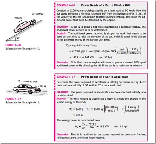
Likewise, when a body is accelerated, its kinetic energy increases. The conservation of energy principle requires that an equivalent amount of energy must be transferred to the body being raised or accelerated. Remember that energy can be transferred to a given mass by heat and work, and the energy transferred in this case obviously is not heat since it is not driven by a temperature difference. Therefore, it must be work. Then we conclude that (1) the work transfer needed to raise a body is equal to the change in the potential energy of the body, and (2) the work transfer needed to accelerate a body is equal to the change in the kinetic energy of the body (Fig. 4–35). Similarly, the potential or kinetic energy of a body represents the work that can be obtained from the body as it is lowered to the reference level or decelerated to zero velocity.
This discussion together with the consideration for friction and other losses form the basis for determining the required power rating of motors used to drive devices such as elevators, escalators, conveyor belts, and ski lifts. It also plays a primary role in the design of automotive and aircraft engines, and in the determination of the amount of hydroelectric power that can be produced from a given water reservoir, which is simply the potential energy of the water relative to the location of the hydraulic turbine.

