CONSERVATION OF MASS PRINCIPLE
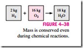
The conservation of mass principle is one of the most fundamental principles in nature. We are all familiar with this principle, and it is not difficult to under- stand. As the saying goes, you cannot have your cake and eat it, too! A person does not have to be an engineer to figure out how much vinegar-and-oil dressing he is going to have if he mixes 100 g of oil with 25 g of vinegar. Even chemical equations are balanced on the basis of the conservation of mass principle. When 16 kg of oxygen reacts with 2 kg of hydrogen, 18 kg of water is formed (Fig. 4–38). In an electrolysis process, this water will separate back to 2 kg of hydrogen and 16 kg of oxygen.
Mass, like energy, is a conserved property, and it cannot be created or destroyed. However, mass m and energy E can be converted to each other ac- cording to the famous formula proposed by Einstein:
where c is the speed of light. This equation suggests that the mass of a system will change when its energy changes. However, for all energy interactions en- countered in practice, with the exception of nuclear reactions, the change in mass is extremely small and cannot be detected by even the most sensitive de- vices. For example, when 1 kg of water is formed from oxygen and hydrogen, the amount of energy released is 15,879 kJ, which corresponds to a mass of 1.76 X 10⁻¹⁰ kg. A mass of this magnitude is beyond the accuracy required by practically all engineering calculations and thus can be disregarded.
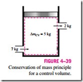
For closed systems, the conservation of mass principle is implicitly used by requiring that the mass of the system remain constant during a process. For control volumes, however, mass can cross the boundaries, and so we must keep track of the amount of the mass entering and leaving the control volume (Fig. 4–39).
Mass and Volume Flow Rates
The amount of mass flowing through a cross section per unit time is called the mass flow rate and is denoted m· . Again the dot over a symbol is used to indicate a quantity per unit time.
A fluid flows in or out of a control volume through pipes (or ducts). The mass flow rate of a fluid flowing in a pipe is proportional to the cross- sectional area A of the pipe, the density r, and the velocity ‘V of the fluid. The mass flow rate through a differential area dA can be expressed as
In most practical applications, the flow of a fluid through a pipe or duct can be approximated to be one-dimensional flow, and thus the properties can be assumed to vary in one direction only (the direction of flow). As a result, all properties are uniform at any cross section normal to the flow direction, and the properties are assumed to have bulk average values over the cross section. However, the values of the properties at a cross section may change with time unless the flow is steady.
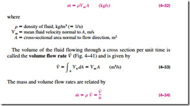
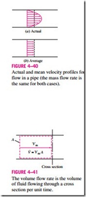
The one-dimensional-flow approximation has little impact on most proper- ties of a fluid flowing in a pipe or duct such as temperature, pressure, and density since these properties usually remain constant over the cross section. This is not the case for velocity, however, whose value varies from zero at the wall to a maximum at the center because of the viscous effects (friction between fluid layers). Under the one-dimensional-flow assumption, the velocity is assumed to be constant across the entire cross section at some equivalent aver- age value (Fig. 4–40). Then the integration in Eq. 4–31 can be performed for one-dimensional flow to yield
This relation is analogous to m = V/u, which is the relation between the mass and the volume of a fluid in a container.
For simplicity, we drop the subscript on the mean velocity. Unless otherwise stated, ‘V denotes the mean velocity in the flow direction. Also, A denotes the cross-sectional area normal to the flow direction.
Conservation of Mass Principle
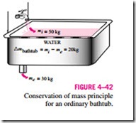
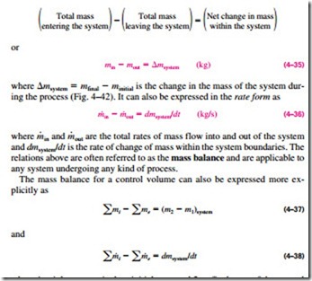
The conservation of mass principle can be expressed as: net mass transfer to or from a system during a process is equal to the net change (increase or decrease) in the total mass of the system during that process. That is,
where i = inlet; e = exit; 1 = initial state and 2 = final state of the control volume; and the summation signs are used to emphasize that all the inlets and exits are to be considered.
When the properties at the inlets and the exits as well as within the control volume are not uniform, the mass flow rate can be expressed in the differential form as dm· = r’Vn dA. Then the general rate form of the mass balance (Eq. 4–38) can be expressed as
to account for the variation of properties. The integration of dmCV = r dV on the right-hand side over the volume of the control volume gives the total mass contained within the control volume at time t.
The conservation of mass principle is based on experimental observations and requires every bit of mass to be accounted for during a process. A person who can balance a checkbook (by keeping track of deposits and withdrawals, r simply by observing the “conservation of money” principle) should have no difficulty in applying the conservation of mass principle to engineering systems. The conservation of mass equation is often referred to as the continuity equation in fluid mechanics.
Mass Balance for Steady-Flow Processes
During a steady-flow process, the total amount of mass contained within a control volume does not change with time (mCV = constant). Then the conservation of mass principle requires that the total amount of mass entering a control volume equal the total amount of mass leaving it (Fig. 4–43). For a garden hose nozzle, for example, the amount of water entering the nozzle is equal to the amount of water leaving it in steady operation.
When dealing with steady-flow processes, we are not interested in the amount of mass that flows in or out of a device over time; instead, we are interested in the amount of mass flowing per unit time, that is, the mass flow rate m· . The conservation of mass principle for a general steady-flow system with multiple inlets and exits can be expressed in the rate form as (Fig. 4–44)
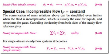
where the subscript i stands for inlet and e for exit. Many engineering devices such as nozzles, diffusers, turbines, compressors, and pumps involve a single stream (only one inlet and one exit). For these cases, we denote the inlet state by the subscript 1 and the exit state by the subscript 2. We also drop the summation signs. Then Eq. 4–40 reduces, for single-stream steady-flow sys- tems, to
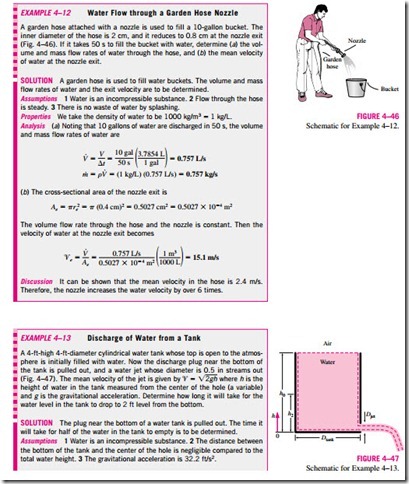
It should always be kept in mind that there is no such thing as a “conservation of volume” principle. Therefore, the volume flow rates into and out of a steady-flow device may be different. The volume flow rate at the exit of an air compressor will be much less than that at the inlet even though the mass flow rate of air through the compressor is constant (Fig. 4–45). This is due to the higher density of air at the compressor exit. For liquid flow, however, the volume flow rates, as well as the mass flow rates, remain constant since liquids are essentially incompressible (constant-density) substances. Water flow through the nozzle of a garden hose is an example for the latter case.
