Influence of variables
There are many parameters associated with both the impacting particles and the sur- face material that will have an effect on erosive wear. In some cases the variables are inter-related and so need to be considered in groups in these situations.
Impact angle and surface material
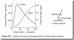
A curve presented by Tilly [1] and shown in Figure 23.1 illustrates the variation of ero- sion with impact angle for two different surface materials and is typical of the early work carried out to investigate the influence of these variables.
Both materials showed very significant differences in both erosion rate and the effect of impact angle. These materials do, in fact, exhibit characteristic types of behaviour that are now well recognized. The aluminium alloy is typical of ductile materials: it suffers maximum erosion at an impact angle of about 20° and offers good erosion resistance to normal impact. The glass is typical of brittle materials: it suffers severe erosion under normal impact but offers good erosion resistance to low angle, glancing impact. These particular tests were carried out with sand particles sieved to between 60 and 125 j.Lm and impacted at about 100 m/s. That brittle and ductile mater- ials respond to erosion in very different ways can be clearly seen from Figure 23.1, and it is obvious that different mechanisms of material removal must be involved.
The influence of impact angle and the different response of ductile and brittle materials to erosive wear is an aspect of the problem that will be considered at many different points. The relationships can be used to explain a number of observed phenomena in erosive wear, and are particularly useful in predicting the possible behaviour in new and untried situations.
Theories proposed
From early thoughts on the matter it was suggested that for ductile materials (annealed low carbon steel, copper, aluminium, etc.) material removal is predominantly by plas- tic deformation. No cracks propagate ahead of the cutting particle and the volume removed is due entirely to the cutting action of the particle, rather like the cutting edge of a machine tool. For brittle materials (glass, basalt, ceramics, cast iron, concrete, etc.) it was thought that material removal is in a large part due to the propagation of fracture surfaces into the material.
These erosion processes, however, have subsequently proved to be not quite as straightforward as this. Photographs taken of impact craters, produced as a result of single particle impact studies, have shown clear evidence that melting has taken place [2, 3]. The melting only occurs over a small part of the impact crater, but it must be considered as being contributory to the erosive wear process. This is considered later in relation to heat treated surface materials.
Velocity
Of all the variables that influence the problem of erosive wear, velocity is probably the most important of all. It is generally recognized that erosive wear is dependent upon a simple power of velocity, such as:
Surface material
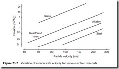
There is much confusion as to the value of the exponent, and values of n ranging from 2–6 have been reported. Tilly and Sage [4] tested a wide range of different materials and obtained very good agreement with respect to the exponent, n, in each case. Their results are reproduced in Figure 23.2. This is a log plot and the slope of all the lines was approximately 2.3. The velocities, of course, are well above those generally encoun- tered in pneumatic conveying systems, even at the lower end of their range.
The velocity exponent is now generally considered to be approximately 21⁄2, and although erosive wear resistance varies widely for different surface materials, as shown in Figures 23.1 and 23.2, the value of the velocity exponent remains reasonably constant at about 21⁄2 for all surface materials.
Bend wear
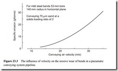
Few comprehensive erosion studies have been carried out exclusively in the velocity range appropriate to pneumatic conveying. The author, however, has carried out sev- eral extensive research programmes into the erosion of pipe bends in an actual pneu- matic conveying system, at velocities appropriate to dilute phase suspension flow [5]. Tests were carried out over a range of conveying air velocities from 15–35 m/s and at solids loading ratios from 0.5 to 8. Steel bends of 53 mm bore having a bend diameter, D, to pipe bore, d, ratio of about 5:1 were eroded by 70 and 230 j.Lm sand, and over the ranges tested the velocity exponent was found to be consistent at 2.65. A graph show- ing the influence of conveying air velocity on the specific erosion of the bends is given in Figure 23.3.
The erosion is in terms of the mass of metal eroded from a bend per tonne of sand conveyed through the bend. With a velocity exponent of 2.65 it means that the wear rate will increase by a factor of six with a doubling of the air velocity. This explains why the curve rises so steeply in Figure 23.3. If a positive pressure conveying system
operates at a pressure of 1 bar gauge, a doubling of the velocity will be achieved in a single bore pipeline discharging to atmospheric pressure. With a vacuum conveying system a doubling in velocity will be achieved with a system exhausting at 0.5 bar absolute. In such a system a bend at the end of the pipeline will wear approximately six times as fast as a bend at the start of the pipeline.
If an abrasive material is to be conveyed, therefore, it would always be recom- mended that the pipeline be stepped to a larger bore part way along its length in order to limit the maximum value of velocity that is achieved, in order to minimize the erosive wear of bends towards the end of the pipeline. It is essential, of course, that the step to the larger bore pipeline is correctly positioned along the pipeline, for if the velocity falls below the minimum value of conveying air velocity at the step, the pipe- line is likely to block at this point.
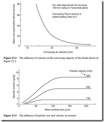
Figure 23.3 shows quite clearly that excessively high conveying air velocities should be avoided. It also shows the benefits of conveying with low velocity air, and hence the potential of low velocity flow in this respect. With the bends reported in Figure 23.3, tested at a solids loading ratio of 2, bend failure occurred when about 60 g of metal was eroded from the bend. The bend wall thickness was about 4 mm. In Figure 23.4 the conveying capacity of these bends, in terms of the mass of sand that could be conveyed through the pipeline before bend failure occurred, is presented. From this it will be seen that with a conveying air velocity of about 30 m/s only 3 tonne of sand could be conveyed before bend failure.
Particle size
The general consensus of opinion with regard to particle size is that there is a thresh- old value of wear rate which, for velocities appropriate to pneumatic conveying, occurs at a particle size of about 60 j.Lm. Below this size wear rate reduces, but for
particle sizes greater than 60 j.Lm it remains constant. Results of work carried out by Tilly [6] are presented in Figure 23.5.
Figure 23.5 shows that the threshold value increases with increase in velocity. The work was carried out for an investigation into the erosion of aircraft engines, which explains the high velocity range. A shot blast type of test rig, in which abrasive par- ticles were impacted against flat plates, was used for the purpose.
Wear rate here is expressed in specific terms, that is the mass (or volume) of sur- face material eroded per unit mass of particles impacted. In a given mass of particles, the number of particles will reduce as the particle size increases, and so although the specific erosion remains constant with increase in particle size, the erosive wear per particle will increase approximately with the cube of the particle size. Little work has
been undertaken with particles much larger than about 1 mm in size and so it is not known to what particle size the threshold value remains constant.
Bend wear
Work carried out on actual pipe bends in pneumatic conveying system pipelines would tend to confirm this [7]. Batches of sand with mean particle sizes ranging from 70 to 280 j.Lm were used in a programme of conveying trials. Six test bends in the one pipeline were monitored for erosive wear, and the average mass eroded from each bend was found to be independent of particle size. On an individual basis, however, the bends showed a very interesting trend. The degree of scatter in the results increased markedly with decrease in particle size, as shown in Figure 23.6. With the larger particles the wear rates were remarkably consistent, but with the finer particles the spread of the results was very wide.
It is believed that the finer particles are influenced by the secondary flows and tur- bulence that can be generated by the bends and that this causes accelerated wear of some bends, although there is no obvious reason why some bends were more vulner- able than others in the pipeline. This could well account for some of the premature failures that have been reported in situations where very fine materials have been con- veyed. It was also found that the depth of penetration of the particles into the bend walls was a factor of two greater for the 70 j.Lm sand compared with the 280 j.Lm sand. Since failure occurs when a given thickness of material is eroded, this parameter is potentially as important as specific erosion in pipe wear situations.
Particle hardness
The value of the particle hardness of the material being conveyed is the major indica- tor of the potential erosiveness of the material. Goodwin et al. [8] investigated the influence of particle hardness on erosive wear with a rig in which abrasive particles
were impacted against test plates. They found that erosion is related to hardness by the expression:
Erosion = constant X H 2.4
where Hp is the particle hardness (kg/mm2).
It is generally considered, however, that there is a threshold value of particle hardness beyond which erosion remains essentially constant. This occurs at a particle hard- ness of about 800 kg/mm2, and so materials with hardness values much greater than this would not be substantially more erosive than sand particles.
Bend wear
A sketch of the potential influence of particle hardness on the erosion of mild steel bends, from work of the author, is given in Figure 23.7. The hardness values of typical materials, both potential conveyed materials and bend surface materials, have been superimposed for reference.
It will be noticed from this that coal is a very soft material and is unlikely to be a problem with respect to erosion. In reality, of course, both pulverized and granular coal are erosive materials. This, however, is due to the presence of non-combustible min- erals, such as quartz and alumina in the coal, and not to the coal itself. With large tonnage flows, even small percentages of these highly abrasive minerals will cause severe wear. A similar situation applies to pulverized fuel ash, and other materials containing small percentages of similar contaminants, such as barytes and wood chips.


