Pressure control valves
We have already briefly discussed what a pressure control valve is and what it does in a hydraulic system. This section is designed to give a deeper understanding of the concept of manipulating force through a hydraulic system using pressure control valves and to also illustrate the operating and design principles of the various types of pressure control valves and their applications. The two basic pressure control valve design types are:
1. Direct-acting pressure control valves and
2. Pilot-operated pressure control valves.
The operating principles of all the pressure control valves revolve around these two basic design types.
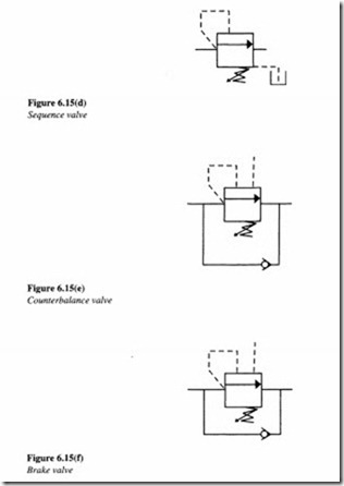
The primary objective in any hydraulic circuit is to either control the flow rate or pressure. For accurate control of force in a hydraulic circuit, six different types of pressure control valves have been developed. These are given below along with their graphical representation (Figures 6.15 (a)-(f)).
One may find the graphical symbols quite confusing since these valves resemble one another so closely that often only their location in a hydraulic circuit may actually help determine what type of pressure valve they are.
Simple pressure relief valve
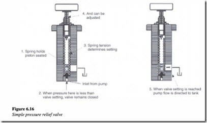
The most widely used type of pressure control valve is the pressure relief valve since it is found in practically every hydraulic system. It is a normally closed valve whose function is to limit the pressure to a specified maximum value by diverting the pump flow back to the tank. The primary port of a relief valve is connected to system pressure and the secondary port connected to the tank. When the poppet in the relief valve is actuated at a predetermined pressure, a connection is established between the primary and secondary ports resulting in the flow getting diverted to the tank. Figure 6.16, illustrates the operation of a simple direct acting relief valve.
A poppet is held seated inside the valve by the direct force of a mechanical spring which is usually adjustable. The poppet is kept closed by the spring tension set on the knob until the system pressure working against the poppet reaches the cracking pressure. The poppet is forced off its seat when the system pressure reaches full relief value. This permits fluid flow across the poppet to the tank. Thus the required pressure in the system is maintained as per the set value on the pressure relief valve.
When the hydraulic system does not accept any flow due to a safety reason in the system, the pressure relief valve releases the fluid back to the tank to maintain the desired system pressure in the hydraulic circuit. It provides protection against any overloads experienced by the actuators in the hydraulic system. One important function of a pressure relief valve is to limit the force or torque produced by the hydraulic cylinders and motors.
One important consideration to be taken note of is the practical difficulty in designing a relief valve spring strong enough to keep the poppet closed at high-flow and high pressure conditions. This is normally the reason why direct acting relief valves are available only in relatively smaller sizes.
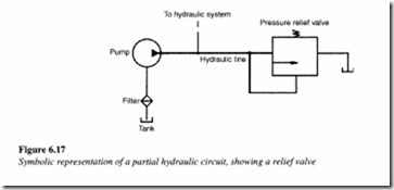
A partial hydraulic circuit consisting of a pump and a pressure relief valve has been depicted in Figure 6.17. The pump and the relief value are symbolically represented.
A compound pressure relief valve is one which operates in two stages. They are designed to accommodate higher pressures than direct acting relief valves at the same flow rate capacity. To have a broad understanding of how a compound pressure relief is internally designed, a cutaway view of an actual valve manufactured by Vickers INC., Detroit is shown in Figure 6.18.
The first stage of the pilot relief valve includes the main spool which is normally closed and kept in position by a non-adjustable spring. The pilot stage is located in the upper valve body and contains a pressure-limiting poppet, which is held against a seat by an adjustable spring. The lower body contains the port connections. The balanced piston in the lower part of the body accomplishes diversion of the full pump flow.
In normal operation, the balanced piston is in a condition of hydraulic balance. Pressure at the inlet port acts on both sides of the piston, through an orifice, that is drilled through the large land. For pressures less than the valve setting, the piston is held on its seat by a light spring. As soon as the pressure reaches the setting of the adjustable spring, the poppet is forced off its seat. This limits the pressure in the upper chamber. The restricted flow through the orifice into the upper chamber results in an increase in pressure in the lower chamber. This causes an imbalance in the hydraulic forces, which tends to raise the piston off its seat. When the pressure difference between the upper and the lower chamber reaches approximately 1.5 kg/cm2 (approx. 21 psi) the large piston lifts off its seat to permit flow directly to the tank.
If there is a flow increase through the valve, the piston lifts further off its seat. However, this compresses only the light spring and hence very little override occurs. Compound relief valves can also be operated remotely by using the outlet port from the chamber above the piston. This chamber in turn can be vented to the tank through a solenoid-operated direction control valve.
Pressure-reducing valve
Pressure-reducing valves are normally open pressure control valves that are used to limit pressure in one or two legs of a hydraulic circuit. Reduced pressure results in a reduced force being generated. This is the only pressure control valve which is of the normally open type (Figure 6.19(a)). A typical pressure-reducing valve and its function is described below (Figure 6.19(c)).
This valve is actuated by the downstream pressure and tends to close as the pressure reaches the valve setting. When the downstream pressure is below the valve setting, fluid will flow freely from the inlet to the outlet. Observe that there is an internal passage from the outlet, which transmits the outlet pressure to the spool end opposite the spring. When the downstream pressure increases beyond the value of the spring setting, the spool moves to the right to partially block the outlet port as shown in Figure 6.19(b). Just enough flow is thus passed through the outlet to maintain its preset pressure. If the valve closes completely, leakage past the spool could cause the downstream pressure to build above the set pressure of the spring. This is prevented from occurring by allowing a continuous bleeding to the tank through a separate drain line.
Practical application of a pressure reducing valve in a hydraulic system
Let us consider a hydraulic circuit where one cylinder is required to apply a lesser force than the other as shown in Figure 6.20. Here cylinder B is required to apply a lesser force than cylinder A. This is accomplished as follows.
A pressure-reducing valve is placed just before cylinder B in the hydraulic circuit as shown. This arrangement allows flow to the cylinder, until the set pressure value on the valve is reached. At this point where the set pressure is reached, the valve shuts off, thereby preventing any further buildup of pressure. The fluid is bled to the tank through the drain valve passage resulting in the easing-off of the pressure, as a result of which the valve opens again. Finally a reduced modulated pressure equal to the valve results.
Unloading valve
Unloading valves are remotely piloted, normally closed pressure control valves, used to direct flow to the tank when pressure at a particular location in a hydraulic circuit reaches a predetermined value. Figure 6.21 depicts the sectional view of a typical unloading valve used in hydraulic systems.
The unloading valve in Figure 6.21 is used to unload pressure from the pump connected to port A, when the pressure at port X is maintained at a value satisfying the valve setting. The spring-loaded ball exercises control over the high-flow poppet along with the pressure applied at port X. Flow entering at port A is blocked by the poppet at low pressures. The pressure signal from port A passes through the orifice in the main poppet to the top side area and then to the ball. There is no flow through these sections of the valve until the pressure rise equals the maximum value permitted by the spring-loaded ball. When that occurs, the poppet lifts causing fluid flow from port A to port B which in tum is connected to the tank. The pressure signal at port X acts against the solid control piston and forces the ball further off the seat. Due to this, the topside pressure on the main poppet reduces and allows flow from port A to B with a very low-pressure drop, as long as the signal pressure at port X is maintained.
Application
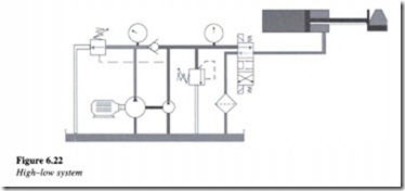
A typical example of an unloading valve application is a high-low system consisting of two pumps, one a high displacement pump and the other a low displacement pump as shown in Figure 6.22.
This system shown above is designed for providing a rapid return on the work cylinder. In this system, the net total displacement of both the pumps is delivered to the work cylinder until the load is contacted. At this point there is an increase in system pressure and this causes the unloading valve to open. This results in the flow from the high displacement pump getting directed back to the tank at a minimal pressure. The low volume pump continues to deliver flow for the higher pressure requirement of the work cycle. For facilitating rapid return of the cylinder, flow from both the pumps is again utilized.


