Gear Pumps
A gear pump develops flow by carrying fluid between the teeth of two meshed gears. One gear is driven by the drive shaft and turns the other. The pumping chambers formed between the gear teeth are enclosed by the pump’s housing and the side plates.
A partial vacuum is created at the inlet as the gear teeth unmesh. Fluid flows in to fill the space and is carried around the outside of the gears. As the teeth mesh again at the outlet, the fluid is forced out. High pressure at the pump’s outlet imposes an unbalanced load on the gears and their bearing support structure.
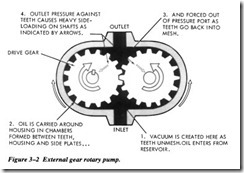
Gear pumps are classified as either external or internal gear pumps. Inexternal gear pumps, the teeth of both gears project outward from their centers (Figure 3-2). External gear pumps may use spur, herringbone, or helical gear sets to move the fluid.
External Gear Pumps
In this design, the pumping chambers also are formed between the gear teeth. A cres cent seal is machined into the pump body between the inlet and outlet where clear ance between the teeth is at its greatest.
Also in this general family of gear pumps is the lobe or rotor pump. This pump operates on the same principle as the external gear, but has a higher displacement.
Spur Gear Pumps
The spur gear pump, shown in Figure 3-2, consists of two meshed gears, which revolve in a housing. The drive gear in the illustration is turned by a drive shaft, which is attached to the power source. The clearances between the gear teeth as they mesh and between the teeth and the pump housing are very small.
In Figure 3-2, the drive gear is turning in a counterclockwise direction and the driven gear is turning in a clockwise direction. As the teeth pass the inlet port, liquid is trapped between the teeth and the housing. This liquid is carried around the housing to the outlet port. As the teeth mesh again, the liquid between the teeth is pushed into the outlet port. This action produces a positive flow of liquid into the system. A shear pin or shear sec tion is incorporated in the drive shaft. This is to protect the power source or reduction gears if the pump fails because of excessive load or the jamming of parts.
Herringbone Gear Pumps
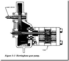
The herringbone gear pump (Figure 3-3) is a modification of the spur gear design. The liquid is pumped in the same manner as in the spur gear pump. However, in the
herringbone pump, each set of teeth begins its fluid discharge phase before the pre ceding set of teeth has completed its discharge phase. This overlapping and the relatively larger space at the center of the gears tend to minimize pulsations and give a steadier flow than the spur gear pump.
Helical Gear Pumps
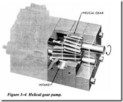
The helical gear pump (Figure 3-4) is still another modification of the spur gear design. Because of the helical gear design, the overlapping of successive discharges from spaces between the teeth is even greater than it is in the herringbone design. Therefore, the discharge flow is smoother. As a result, the gears can be designed with a small number of large teeth, thus allowing an increase in capacity without sacrificing smooth flow.
The gear sets in this type of pump are driven by a set of timing gears that help maintain the required close tolerance between mating gears without actual metal-to-metal con tact. Metallic contact between the teeth would provide a tighter seal against hydraulic slip, but it would also decrease volume and dramatically increase wear of the teeth.
Anti-friction bearings at both ends of the gear shafts maintain proper alignment and radial clearance between gears and minimize the friction loss in the transmitted power. Suitable packing is used to prevent leakage around the shaft.
Internal Gear Pumps
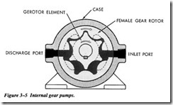
In an internal gear pump, the teeth of one gear project outward from the gear hub, the teeth of the other gear projects inward toward the center of the pump (Figure 3-5, view A). Internal gear pumps may be either centered or off-centered. Figure 3-5 illustrates two types of internal gear pumps. Pump A is an example of a centered pump, and pump B is off-centered.
Off-Centered Internal Gear Pumps
In this type of pump, the drive gear is attached directly to the drive shaft of the pump and is placed off-center in relation to the internal gear. The two gears mesh on one side of the pump, between the suction and discharge ports. On the opposite side of the chamber, a crescent-shaped form fitted to a close tolerance fills the space between the two gears.
The rotation of the center gear by the drive shaft causes the outside gear to rotate, since the two gears are meshed. Everything in the chamber rotates except the crescent. This causes liquid to be trapped in the gear spaces as they pass the crescent. The liquid is carried from the suction port to the discharge port, where it is forced out of the pump by the meshing gears. The size of the crescent that separates the internal and external gears determines the volume delivered by the pump. A small crescent allows more volume of liquid per revolution than a larger crescent.


