AIR DRYERS
Air dryers remove or modify the water content of air. Moisture is a general term applying to the liquid water aerosol content of air and its water vapour content. No single device can remove all the moisture but a combination of devices can be used to reduce it to an acceptably low level. The ability of air to hold water vapour is dependent on temperature, see Figure 1, so cooling the air allows some of the vapour content to condense, which can then be removed. For every 11oc rise in temperature the water vapour holding capacity
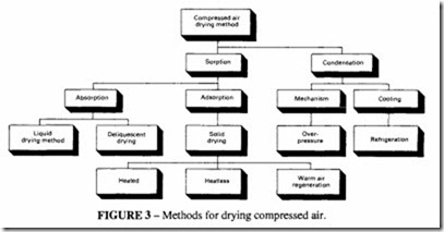
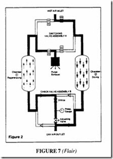
Methods used for air drying in industry are varied and many types of equipment have been used for the purpose (see Figures 2 and 3). The conditions of the application and the intended service of the air greatly affects the method required to dry it and the choice of equipment to perform the function.
Air is dried in industry for reasons varying from room air conditioning for comfort and warehouse air conditioning to prevent corrosion, to compressed air services for pneumatic tools and instrumentation, where moisture could cause equipment malfunction, product spoilage and corrosion. Examples of the advantages of dry compressed air are:
• Supply to air tools making it possible to lubricate them more effectively. Risk of icing in the exhaust is reduced.
• Lubrication of pneumatic components is improved when dry air is used and servicing intervals are extended.
• The use of dry air in paint spraying equipment eliminates risk of damage to the finish from water droplets.
• In blast cleaning units, the reliability of the equipment is improved and risks of icing under outdoor conditions are eliminated.
In a dry air system, there is no corrosion which can lead to loss of pressure and leaks.
No need for draining off condensed water.
Air drying is desirable in conditions of high ambient temperatures and low humidity such as laundries, where it may be otherwise difficult to secure sufficiently low com pressed air temperatures to provide ideal conditions for air line filters.
Different degrees of dryness (dewpoint) are required, depending on the use of the compressed air, the ambient temperatures and the humidity.
Three basic processes are used for the removal of moisture from air; these are:
• Momentum transfer Heat transfer
Mass transfer
Mechanical separation devices based on momentum transfer can only remove the aerosols; they cannot remove water vapour. Heat exchangers and refrigeration systems condense and remove the water vapour by heat transfer. Adsorption and absorption systems use mass transfer to remove the water vapour. The characteristics of each are shown in Table 1.
The primary types of mechanical separation devices are:
Coalescing filters
• Impingement separators
• Centrifugal force separators
• Receivers
• Expansion and evaporation devices
The principle of the coalescing filter is described in the chapter on Compressed Air Filtration. Coalescing filters are the mostefficientaerosol separators, capable of removing in excess of 99% of the entrained water. Impingement separators are Jess effective, removing 98%. Centrifugal separators are least effective with about 90% removal.
Receivers reduce the aerosol content by settling, due to the low velocity of the air flowing through. They are effective at removing the large droplets.
Expansion and evaporation devices do not actually remove any water, but cause evaporation of the liquid aerosols after impact on a solid surface.
Thermal devices used for drying are: heat exchangers, refrigeration systems, chillers and regenerative heat exchangers.
Counter-current heat exchangers reheat cooled, dried air, causing a reduction in its relative humidity, pre-chilling the incoming air while simultaneously reducing the energy consumption of the system.
Over-pressure
Over-pressure occurs when air is compressed beyond the required working pressure, cooled and expanded to the required pressure. Because of the higher pressure, the volume is reduced and as the air is cooled, its ability to hold water is also reduced. On expansion, the air after the condensate is removed can reach the required dewpoint. The disadvantage of this system is the high energy usage making it useful only for small air flows, although the mechanism works naturally in many compressed air systems.
Refrigeration systems
The ability of air to hold water is dependent on temperature. The traditional method of removing water is by an aftercooler with refrigeration dryers. An aftercooler is a heat exchanger used to cool compressed air after leaving the compressor. Cooling reduces the temperature and precipitates the water into droplets which can be drained off. It also reduces the volume of the air but this represents no power loss (other than that required to run the cooler). As a general rule, air-cooled aftercoolers are used with air-cooled compressors and water cooled aftercoolers with water cooled compressors.
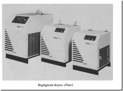
Refrigeration dryers use the simplest drying method; the air passes through an aftercooler but the coolant is maintained at a much lower and constant temperature. The coolant is produced by a closed refrigeration circuit incorporating a compressor and condenser, adjusted to cool the air to between 2°C and 5°C; the limitation of this type of dryer is the freezing point of water, however it is not practical to reduce the temperature completely down to 0°C.
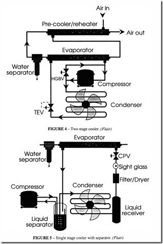
Cooling is done in two stages; first in a pre-cooler which cools with the cool air leaving the dryer, followed by the main cooler using refrigerated coolant. If the water condensed in these coolers is about 2°C, the dryness is adequate for most purposes. In fact drying the
air to a dewpoint about 1ooc less than the prevailing ambient temperature is usually
sufficient to eliminate risk of water condensate in the system. Figure 4 illustrates the system. Note that an internal compressor provides the energy to pump refrigerant round the circuit and represents a small power loss. The thermal expansion valve (TEV) controls the flow of refrigerant to meet demand. As the cool refrigerant passes through the evaporator, heat exchange from the warm compressed air evaporates the refrigerant to a gaseous state, which then re-enters the compressor.
At times oflow demand little or no warm air passes through the evaporator, hence the refrigerant is not warmed and remains in the liquid state. If liquid were allowed to enter the compressor, damage could occur. To prevent this, the hot gas by-pass valve (HGBV) is provided which taps warm gas from the outlet of the compressor to evaporate any liquid droplets remaining. Although this system should be fail-safe, HGBVs are notoriously unreliable, and a malfunction could be expensive. To overcome this an alternative system has been developed, as shown in Figure 5.
In this system, at times of low demand, the gas containing liquid is passed directly to a liquid separator, where the liquid settles at the bottom and the warmer gas is passed to the compressor. The hot gas leaving the compressor is passed through the separator housing , evaporating the settled liquid as well as pre-cooling the refrigerant gas prior to its entering the condenser. The liquid separator has the advantage of simplicity without the need for extra sensors and valves and reduces the servicing costs.
Lower dewpoints than this are required, for example in systems which have pipes outside in cold weather, for some chemical processes and for instrumentation.
Chillers and regenerative heat exchangers are modifications of the normal refrigeration process. In a chiller system, a brine or glycol solution is circulated between the refrigerant evaporator and the air cooler. Because heat transfer is more efficient between the freon of the refrigerator and the liquid coolant, the evaporator can be made smaller and less expensive; improved temperature control is also possible in a chiller. In refrigeration systems with regenerative heat exchangers, the air is cooled below the freezing point of the condensate, and the heat exchanger is either rotated or cycled to permit removal of the ice by defrosting. Such systems need complex controls to function properly.
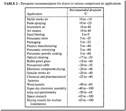
Table 2 gives dewpoint recommendations for dryers for various applications.
Sorption systems
These reduce the water vapour content and the relative humidity. They dry air at constant temperature, based on the mass transfer of water vapour into or onto absorbents or adsorbents. They can be either regenerative or non-regenerative. Regenerative systems can be continuous or alternating. The primary types are;
• Adsorption; non-regenerative adsorbent cartridges and pouches Regenerative adsorbent systems
• Thermally regenerative; temperature swing adsorbers (alternating beds) Continuous rotating bed
• Heatless regenerative types Pressure swing adsorbers (alternating beds)
• Purge stripping Solid absorbent types Deliquescent Non-deliquescent
• Liquid absorbents and membrane separation.
Solid adsorbents remove water vapour by physical forces which attract water molecules to the solid surface of the adsorbent. Solid adsorbent particles are highly porous on a microscopic scale, providing a large area for adsorption. The particles are of the order of I to I 0 mm diameter, to permit high mass transfer rates and allow some aerosol separation by impingement, but at the air velocities permitted for an air adsorption bed, the aerosol removal efficiency for droplets smaller than 10 micron is very low. Common adsorbents used for the removal of water vapour include adsorbent clays, activated aluminium oxide (AhOJ), silica gel (Si02), molecular sieves (Na, AI02) and natural zeolites. Each type of desiccant has its own characteristics, but most are able to produce low effluent dewpoints depending on the adsorbent system and the mode of regeneration.
Adsorption dryers
The adsorption drier consists of two drying columns filled with desiccant (silica gel or alumina). The air passes through one column where thedesiccantadsorbs the water vapour in the air until it is saturated. The airflow is then automatically switched to the second column, while the first column is regenerated, by removing the water from it. Two different methods are used to regenerate the desiccant: in the first method, a separate flow of dry heated air is blown through it; in the second method, no heat is needed but a proportion of the already dried air from the active column is passed through it. The adsorption process is exothermic and the desorption process is endothermic, so it is advantageous to situate the two processes close together to take advantage of heat transfer between the two columns. Both methods waste a proportion of the air to satisfy the purge requirements. The heatless method naturally wastes more, the proportion depending on the inlet temperature and the required dewpoint; the nominal purge air consumption (based on say, a dewpoint of -20°C and an inlet temperature of 35°C) will be about 15% of the rated capacity), but for higher inlet temperatures and a lower required dewpoint, the proportion may be as much as 25%. With a good control system, the energy loss can be minimised. The heat regenerated type uses about 1.5% of the expanded dry air, but requires energy input in the form of heat.
The decision as to which type to choose depends on a calculation of the total energy input. The heatless type is normally the most expensive in running costs because of the wasted air. To save energy, some of the heat of compression may be used to supply regeneration heat if the system can be so designed.
An example of the operation of a heatless dryer is shown in Figures 6 and 7. The first stage in drying the air is the removal of all liquid contaminants, so that the desiccant dryer can
operate at maximum efficiency by removing the vapour only. In Figure 6, wet incoming air passes through a switching valve assembly A, and is directed downwards through chamber 1 where it contacts the desiccant. Air drying takes place by adsorption, which occurs when the moisture level in the air stream is greater than the moisture level in the desiccant. Water vapour in the air stream condenses as a film on the desiccant. Adsorption is an exothermic process, which means that as drying takes place, heat is released and is stored in the desiccant bed for use in the next cycle. Dry air exits chamber 1 and passes through check valve assembly B and continues to the application main.
While gas is being dried in chamber 1, the desiccant in chamber 2, which has been wetted in the previous cycle is being regenerated. At the start of its regeneration, chamber 2 is depressurised from the operating pressure to atmospheric, allowing flow in an upward direction through valve assembly A; the air goes out through the purge exhaust. A portion of the dry outlet air from chamber 1 passes through valve assembly Band upward through the chamber being regenerated. This dry purge, with the aid of the heat generated during the previous drying period removes the moisture from the desiccant. The purge carries this moisture through valve assembly A and through the purge exhaust. The regenerating purge flow is in the counter direction to that of the drying part of the cycle to ensure desiccant regeneration.
When the regeneration cycle is complete, the chamber being regenerated is repressurised to full operating pressure by closing the purge exhaust. Purge gas continues to flow into the chamber until it pressurises to system pressure. Inlet gas is then switched over to chamber 2 (Figure 7) through valve assembly A for drying. Repressurisation before
switch over ensures that the desiccant will not bejolted by the inrushing gas flow. A drying period of about 3 minutes provides an effluent dewpoint of -40 °C or better. A full three minutes is used for the drying period . However during the regeneration process, which is occurring in the offstream chamber simultaneously with drying in the onstream chamber, approximately 30 seconds is allowed for chamber pressurisation before going back on stream at switch over. Thus a complete cycle consists of two periods of equal length, one drying, the other depressurisation, regeneration and repressurisation.
Energy efficiency of dryers
The water load on the dryer is determined by the specific flow rate and temperature and is not usually the same as the water load that is present on a continuous basis. For example in the winter, the aftercooler water temperature is lower, decreasing the load on the dryer. Dryers are designed to meet peak conditions. If these peak conditions are not realised, a less severe load is placed on the dryer and energy is wasted in regenerating a desiccant that has not been saturated. It is generally accepted that desiccant dryers may only experience 20 to 30 % of the peak design load; since most dryers work on a fixed cycle, 70 to 80% of the regeneration energy can be wasted, so a system which incorporates the ability to match regeneration energy to moisture load has the capability of saving significant amounts of energy with a resultant cost saving.
Moisture measurement devices
The key to an energy efficient dryer is an accurate, reliable and repeatable moisture measurement device or hygrometer. There are three types of hygrometer for this application, Figure 8:
• in-bed temperature sensing,
• outlet moisture sensing, and
• in-bed moisture sensing.
With in-bed temperature sensing a thermo-switch detects the heat front which passes through the desiccant bed as the heating elements drive off the adsorbed moisture. When
the heat front meets the thermo-switch, the heating is stopped, with a saving in power. This method is not the most efficient, because at low moisture levels, 50% of the energy is used to heat the bed and the chamber and only the remaining 50% is used to drive off water. This technique can only be used in heat activated dryers and not the heatless dryers described above.
Outlet moisture sensors require a hygrometer to be placed at the outlet of the drying chamber to anticipate the breakthrough of the moisture front before it exits the dessiccant. Three types of hygrometers are used for dryer outlet moisture sensing:
• Chemical cells which exhibit a change in electrical resistance as the moisture increases. These are easily contaminated requiring regular recalibration and frequent replacement.
• Plated wire capacitance probes suffer from the same problem of contamination as the chemical cell.
• Photo-optic sensors incorporate a light source which directs light from a miror on to a light sensor. Changes in reflected light are caused by condensation on the mirror surface. A small heater is used to clear the mirror betwen readings. Any contami nation by oil or dessiccant will render the device useless.
All these methods of moisture sensing must be able to measure moisture content of the order of I 0 parts per million at -40°C, with very little error.
In-bed moisture sensing employs a capacitance probe embedded in the desiccant and determines the humidity by measuring the dialectric strength of the desiccant. The adsorption of water vapour by the desiccant changes its capacitance.
In a heat regenerated dryer, the probe controls the drying portion of the cycle. The probe senses the moisture front as it passes through the chamber. The air still has to pass through further desiccant after the probe so good dewpoint performance is assured. It can be positioned in the bed to sense moisture well before an outlet sensor could and ensures an accurate and consistent outlet dewpoint of between -45°C and -42°C. Fail-safe operation of this type of sensor is secured by setting a high limit to the system; the dryer is put into a fixed cycle when the high limit is exceeded. A capacitance probe suffers from the same problems of contamination as the other types described above but can be coated with a contaminant resistant material.
In a heatless dryer, the in-bed probe controls the regeneration portion of the cycle. Due to the short time cycle of this type of dryer, there is insufficient time for a well defined moisture front to be formed: a saturated or perfectly dry bed is counter-productive. The heat of adsorption must be kept within the desiccant bed. This is accomplished by moving a pocket of moisture up and down the chambers, through drying and regeneration cycles without allowing any to escape. The probe controls this movement during the regeneration portion of the cycle, and is the only type which will function in a heatless dryer.
This automatic moisture load control (AMLOC) ensures a reliable measure of the moisture content in the bed and limits the regeneration energy whether it derives from the electric heat or purge air. An in-bed capacitance probe measures the order of200 parts per million, compared with an outlet probe measuring 5 to 7 parts per million, which makes it an industrial measuring device rather than a laboratory instrument. The savings in energy
will depend on the usage- the lower the flow rate the greater the savings, so in a situation where the dryer is not fully utilised during a shift, the savings are greater. A modern dryer, in addition to AMLOC will also incorporate a microprocessor control unit to monitor the dryer condition to identify cycle times and maintenance requirements.
Rotary adsorption dryer
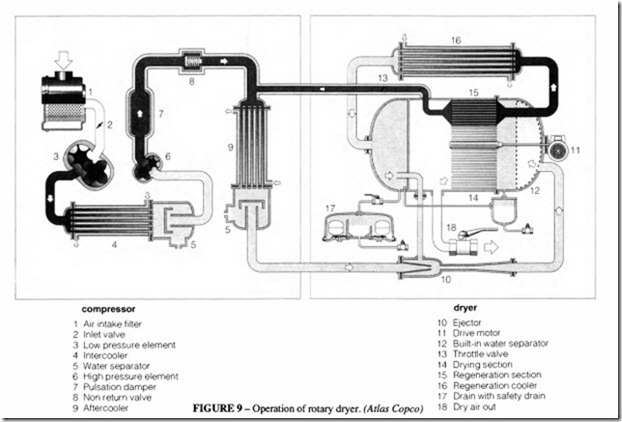
This new development, Figures 9 and I 0, is claimed to be particularly efficient in that no external energy is needed, other than a small amount (0.12 kW in this example) to drive the rotating drum and the power needed for the aftercooler; nor is there any wasted air. This dryer is only suitable where the air from the compressor is completely oil-free. It is currently supplied matched to a range of rotary screw compressors (capacities from 6 to 120m3/min).
The pressure vessel is divided into two sectors, one for drying and one for regenerating. Through these sectors, there rotates a glass fibre based corrugated paper drum impreg nated with silica gel. Hot air leaving the compressor is divided into two streams before reaching the aftercooler. The main stream passes through the aftercooler into the drying sector where the moisture is removed from it through adsorption. The hot air branched before the aftercooler passes through the regeneration sector where it removes moisture from the desiccant by evaporation. This airthen passes through the regeneration aftercooler. Moisture separated from the air is collected and drained by means of an automatic drain system. The cooling can be either by water or by airblast. The pressure dewpoint can be brought down to -40°C if the temperature of the cooling medium is I 0°C.
Absorption dryers
The drying of air by absorption is a true chemical process in that moisture is absorbed into the medium which can be either solid or deliquescent. Solid material reacts with the water vapour without turning it to liquid, whereas in a deliquescent dryer the water vapour is absorbed into the salt until it Iiquifies. Regeneration is impractical, so the drying medium must be changed regularly. Unfortunately, the absorption media are usually highly corrosive. Deliquescent media carry the danger that they become entrained in the air and carry on down the line. The absorption media also have the characteristic that above a temperature of 30°C , the crystals bake together which leads to a high pressure drop. A dewpoint of about l5°C is the best that absorption dryers can achieve.
Non-deliquescent absorbents form solid hydrates when combined with water vapour; they are not dissolved in the process. These are commonly used in desiccant pouches in the same way as solid absorbents.
Liquid absorbents include water solutions of glycol, salts, acids and other water absorbing chemicals, which are cascaded through a mass transfer tower to effect water vapor absorption from the air. Packing or perforated plates are commonly used in such towers to enhance the rate of mass transfer. The liquid absorbent is drained from the bottom of the tower to a reboiler where it is regenerated; it is then recirculated to the top of the tower.
Solid and liquid absorbents are useful in removing large amounts of water vapor from air of high humidity, but they are not capable of reducing the vapour contents to low levels such as can be achieved with refrigerant or adsorption dryers.
Membrane dryers are continuously regenerating absorption devices.
Wet air passes along one side of a membrane, while a dry purge stream is passed along the other side. Water vapour is absorbed into the semi-permeable membrane and is passed through it from one absorption site to another, from the high pressure side to the low pressure side. The effluent quality is dependent upon the permeability of the membrane, the amount of the membrane surface available for transmission of water vapour and the amount of purge air. Commercial systems produce effluent dewpoints comparable with other absorption systems. As with other such systems they are able to remove large quantities of water but are not suitable for very low dewpoints.
Air heating
A similar effect to drying can be achieved for a limited period of time and for a limited length of pipe by inserting a heating unit in the line. A heater does not extract moisture, it merely reduces the relative humidity so that the vapour does not condense out at the point of use. Because expansion through an orifice causes a drop in temperature, there is a possibility of condensation if the temperature is low before the orifice. An air dryer helps to prevent that. It can be used upstream of a paint sprayer to prevent water droplets ruining the finish and for medical and dental applications where a low temperature would be uncomfortable.


