Air only relationships
Introduction
Although few reliable or universal models currently exist for predicting the pressure drop for gas–solid flows in pipelines, models for the single phase flow of a gas are well established. Although discussion will generally be in terms of air, the models presented will work equally well with the appropriate value of the specific gas constant for the particular gas being considered. Gas constants for a range of gases were presented in Section 9.2.3.2 with Table 9.2.
Empty conveying pipeline pressure drop values, for air only, will provide a useful datum for both the potential capability of a system for conveying material and the condition of the pipeline (considered in Chapter 20). Air only pressure drop values for the conveying pipeline also provide a basis for some first approximation design methods for the pneumatic conveying of materials (see Chapter 18).
Air supply and exhaust or venting pipelines can be of a considerable length with some systems, whether for positive pressure or vacuum systems, particularly if the air mover or the filtration plant is remote from the conveying system. In these cases it is important that the air only pressure drop values in these pipeline sections are evaluated, rather than just being ignored, for they could represent a large proportion of the avail- able pressure drop if they are not sized correctly. Air flow control is also important, particularly if plant air is used for a conveying system, or if the air supply to a system needs to be proportioned between that delivered to a blow tank and that directed to the pipeline, for example.
Pipeline pressure drop
The pressure drop in the empty pipeline is a major consideration in the design of a pneumatic conveying system. If a positive displacement blower is used in combination with a long distance, small bore pipeline, for the suspension flow of a material, for example, it is quite possible that the entire pressure drop would be utilized in blowing the air through the pipeline and that no material would be conveyed. The pressure drop for air only in a pipeline is significantly influenced by the air velocity that is required for the conveying of the material. Bends and other pipeline features also need to be taken into account.
The value of the empty line pressure drop for any pipeline will provide a useful indicator of the condition of the pipeline. If a pressure gauge is situated in the air supply or extraction line, between the air mover and the material conveying pipeline, this will give an indication of the conveying line pressure drop. With an empty pipeline it will indicate the air only pressure drop. If this value is higher than expected it may be due to the fact that the line has not been purged clear of material. It may also be due to material build-up on the pipe walls or a partial blockage somewhere in the pipeline.
Flow parameters and properties
In order to be able to evaluate the pressure drop for the air flow in the empty pipeline, various properties of the air and of the pipeline need to be determined. Mathematical models and empirical relationships are now well established for this single phase flow situation, and so conveying line pressure drops can be evaluated with a reasonable degree of accuracy.
Conveying air velocity
This is one of the most important parameters in pneumatic conveying, with the air velocity at the material feed point, at the start of the pipeline, being particularly import- ant. If the conveying air velocity is not specified, therefore, it will usually have to be evaluated from the volumetric flow rate, pipeline bore, and the conveying line inlet air pressure and temperature, as outlined with Equations (9.11) and (9.19).
Air density
The density, p, of air, or any other gas, is given simply by the mass of the gas divided by the volume it occupies:
where m is the mass of gas (kg) and V, the volume occupied (m3).
The Ideal Gas Law, presented with Equation (9.4) applies equally to a constant mass of a gas, as to a constant mass flow rate of a gas, and so:
where R is the characteristic gas constant (kJ/kg · K) Gas constants for a number of gases were presented in Table 9.2.
A particular reference value is that of the density of air at free air conditions. For air R = 0.2871 kJ/kg · K and so at free air conditions of p0 = 101.3 kN/m2 and T0 = 288 K, and its density p = 1.225 kg/m3.
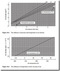
It will be seen from Equation (10.1) that air density is a function of both pressure and temperature, with density increasing with increase in pressure and decreasing with increase in temperature. The influence of pressure and temperature on the density of air is given in Figure 10.1 by way of illustration.
Air viscosity
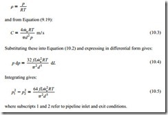
The viscosity, p., of gases can usually be obtained from standard thermodynamic and transport properties tables. In general the influence of pressure on viscosity can be neglected. The influence of temperature on the viscosity of air is given in Figure 10.2 [1].
Friction factor
The friction factor, f, for a pipeline is a function of the Reynolds number, Re, for the flow and the pipe wall roughness, e.
Note:
Reynolds number
![]() where p is the density of air (kg/m3); C, the velocity of air (m/s); d, the pipeline bore (m) and p., the viscosity of air (kg/m · s).
where p is the density of air (kg/m3); C, the velocity of air (m/s); d, the pipeline bore (m) and p., the viscosity of air (kg/m · s).
Alternatively, by substituting p from Equation (10.1) and C from Equation (9.19), give an alternative form:
Values of friction coefficient can be obtained from a Moody chart, a copy of which is given in Figure 10.3.
Typical values of wall roughness, s, are given in Table 10.1 [2].
An accurate value of a surface roughness is clearly not critical, for a 100 per cent error in relative roughness will only result in a 10 per cent error in friction coefficient.
Pressure drop relationships
The pressure drop for straight pipeline, regardless of orientation, is derived in terms of the pipeline friction coefficient. The pressure drop for bends and other pipeline fittings and features is obtained in terms of a loss coefficient. For the total pipeline system the two are added together.
Straight pipeline
The pressure drop for a fluid flowing in a straight pipeline can be determined from Darcy’s equation:
where �p is the pressure drop (N/m2); f, friction coefficient (–); L, the pipeline length (m); p, the density (kg/m3); C, the velocity (m/s) and d, pipe bore (m).
For a compressible fluid such as air, the equation in this form is rather inconvenient, particularly if there is a large pressure drop, for average values of both density and velocity need to be specified, as they are both very pressure dependent. Both density and velocity, however, can be expressed in terms of constants and air pressure, which means that the expression can be easily integrated.
From Equation (10.1):
For a positive pressure system p2 will be specified (usually atmospheric pressure) and so a more useful form of Equation (10.5), which eliminates the unknown pressure p1 is:
Similarly for a negative pressure system p1 will be specified (usually atmospheric) and so an alternative form of Equation (10.5), which eliminates the unknown pressure, p2 is:
Note that R will have to be specified with units of J/kg · K in Equations (10.6) and (10.7).
The influence of air flow rate
The velocity of the conveying air will be approximately proportional to the air flow rate, whether on a mass or a volumetric flow rate basis. From Equation (10.2) it will be seen that pressure drop is proportional to the square of the velocity, and so air flow rate will have a very significant effect on conveying line pressure drop. The influence of velocity is considered in conjunction with pipeline length and bore below.
The influence of pipeline length
From Equation (10.2) it will be seen that pressure drop is directly proportional to pipeline length. Typical values of conveying line pressure drop for a 100 mm bore pipeline are given in Figure 10.4. This is a graph of the conveying line pressure drop for air flow through a pipeline, plotted against the air mass flow rate.
Conveying line exit air velocity values are also given on the air flow rate axis. This clearly shows the adverse effect of air flow rate on pressure drop. It also shows that if a material has to be conveyed over a long distance, the proportion of the total system pressure drop due to the air only in the pipeline will be very significant.
The influence of pipeline bore
From Equation (10.2) it will also be seen that pressure drop is inversely proportional to pipeline bore. Typical values of conveying line pressure drop for a 300 m long pipeline are given in Figure 10.5.
This is a similar plot to that of Figure 10.4. The air mass flow rate axis is proportional to pipe section area, and so conveying line exit air velocities are constant in each case. It can be clearly seen from this plot that the air only pressure drop reduces with increase in pipe bore. If an air mover with a pressure limitation, such as a positive dis- placement blower, has to be used to convey a material over a long distance, therefore, it should be possible to achieve reasonable flow rates with a large bore pipeline.
Bends
The pressure drop for bends in a pipeline can be expressed in terms of a ‘velocity head’:
where k is the number of velocity heads lost for the particular bend geometry and configuration.
Ninety-degree radiused bends are probably the most common pipeline bend. The pressure loss in such a bend will depend upon the ratio of the bend diameter, D, to the pipe bore, d, and the surface roughness. Typical values are given in Figure 10.6 [3]. From this it can be seen that very short radius bends will add significantly to the empty line pressure drop. Minimum pressure drop occurs with bends having a D/d ratio of about 12. This is not a critical value, however, for a reasonably low value of head loss will be obtained with a D/d range from about 5 to 30.
Head losses for radiused bends having a range of bend angles, over a range of D/d ratios, are given in Figure 10.7. A similar plot for sharp angled or mitred bends is given in Figure 10.8 [3]. This shows that the mitred bend will result in the highest value of air only pressure drop for a 90° bend, particularly for smooth pipes.
Equivalent length
The head loss for straight pipeline, as will be seen from Equation (10.2) is given by:
Taking a typical pipeline friction coefficient, f, of 0.005, the equivalent length of a 100 mm bore 90° mitred bend of smooth pipe will be about 5.5 m. If there are a number of such bends in a short pipeline, the bends will add significantly to the total air only pressure drop value.
Other pipeline features
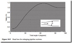
These are treated in exactly the same way as pipeline bends, and in Figures 10.9–10.11 head loss values are given for various pipeline fittings. Expansion fittings are required in stepped pipelines, where the diameter of a line is increased part way along its length in order to reduce the conveying air velocity. Figure 10.9 shows that the air only pressure drop will be a minimum if a tapered section were used having an included angle of about 6°.
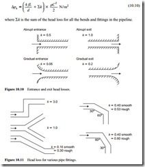
Expansion and contraction sections often occur in association with pipeline feeding systems such as rotary valves, screws and venturis, and at discharge into reception
vessels. Figures 10.9 and 10.10 illustrate the importance of careful design in such devices.
The head loss for various diverter sections, fabricated bends and ‘dog-leg’ sections, that are often used in air supply and exhaust pipelines, are given in Figure 10.11. A comparison of the two ‘dog-leg’ sections shows just how important careful pipeline design and layout are in minimizing pressure drop.
Total pipeline
The pressure drop for the total pipeline is simply given by a summation of all the component pressure drop values, so that:
For convenience the head loss for the pipeline, bends and fittings can be grouped together using the term tf; such that:
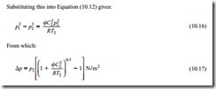
In many cases a value of the conveying line exit air velocity, C2, can be determined. One such derivation was presented as Equation (9.19) and was introduced earlier as Equation (10.3):
Thus in a situation where the downstream pressure, p2, is known (commonly this would be atmospheric pressure in a positive pressure system) and the conveying line exit air velocity can be determined, this expression allows the pressure drop for the air alone to be estimated quite easily.
Alternatively, if the conveying line inlet air velocity, C1, is known, this can be used instead. A substitution of C1 for m.a, from Equation (10.3), into Equation (10.12) gives:
Note:
The velocity, C1, in Equations (10.18) and (10.19), is not the conveying line inlet air velocity which is specified for gas–solid flows in pneumatic conveying. It is the con- veying line inlet air velocity that will result when no material is conveyed. C2 in Equations (10.16) and (10.17), of course, is the same whether material is conveyed or not, since the pressure will always be the same at the end of the pipeline.
Negative pressure systems
For a negative pressure system, p1, will be specified (usually atmospheric). A re-arrangement of Equation (10.18) gives:
Note:
In this case the conveying line inlet air velocity, C1, will be the same whether the material is conveyed or not, since the pressure, p1, will be atmospheric in both cases. This is similar to Equations (10.16) and (10.17) for positive pressure systems.
Air only pressure drop datum
The empty pipeline pressure drop relationships for a pipeline, such as those shown in Figures 10.4 and 10.5, provide a datum for material conveying characteristics and cap- ability. At a given value of air flow rate the pressure drop available must be greater than the air only pressure drop value, otherwise it will not be possible to convey material.
At any value of conveying line pressure drop there will be a corresponding value of air flow rate at which the air only pressure drop will equal the conveying line pressure drop. This value can be determined from Equation (10.13) by making . the subject
of the equation. Such a re-arrangement gives:
This is quite a useful relationship, for it allows an estimate to be made of where the various lines of constant conveying line pressure drop on material conveying characteristics will reach the horizontal axis.

