Compressed air in marine applications
There are several ways in which compressed air finds an application offshore: the supply of breathing air for divers, for engine starting, for operation of air tools on board ship and underwater, air lift dredging and for seismic surveys. Engine starting and air lift dredging are dealt with separately in other chapters.
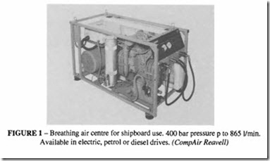
Breathing air is covered in outline in that chapter. For underwater air supply, the pressure requirement may be up to 400 bar and special marine sets are available to supply pressurised and treated air at high pressure, see for example Figure I .
General use of compressed air for marine work
Many of the tools that have been described in the chapters on contractors and industrial tools are suitable for general marine work. Shipboard compressors, both stationary and portable, are supplied by most compressor manufacturers; there may be special regulations which have to be satisfied, e.g. Lloyds or U.S. Coastguard. Stationary compressors using sea water for cooling are supplied by some manufacturers.
Corrosion in the presence of salt-laden air is a problem which should always be borne in mind. Provided that the suppliers are made aware of the use to which their equipment is to be put and any special precautions, particularly in respect of lubrication and maintenance schedules, are strictly followed, there is no reason why most pneumatic equipment should not prove as satisfactory at sea as on land. Tools which are used close to the water line for work on descaling and removal of marine growth are likely to be frequently immersed in water and may require special cleaning after each shift. A useful technique consists in immersing the tool in paraffin or diesel oil to wash out the seawater and then thorough lubrication with oil; for short periods, the tool can be left immersed in the paraffin.
There are some compressed air applications which are of particular interest in offshore applications.
Prospecting with compressed air
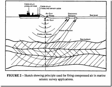
Oceanographic research undertaken to improve our know ledge of the Earth’s structure can make use of compressed air. Figure 2 shows how high pressure air (up to 350 bar) is fired in pulses from special guns at the area being surveyed. The air pulses create shock waves which echo from the survey area, either land mass or sub-strata. The echos are picked up by sensitive electronic devices to provide data on the structure and content of the survey area.
Drill string compensator system
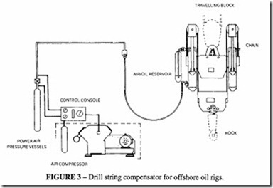
This is a motion compensating system developed to nullify the effects of the heave of the drilling platform or vessel on the drill string or hook supported equipment.
sator shown in Figure 3 comprises two compression-loaded hydraulic-pneumatic cylin ders. The cylinders are supplied with high pressure air which, in the application illustrated, is I63 bar. As the rig heaves upwards, the compensator cylinders retract and the hook moves downwards to maintain the selected drilling load. Thus while the drill platform and compensator move, the hook remains fixed relative to the Earth. Use of these compensa tors ensures that drilling can proceed in high heave conditions.
Use of pneumatic tools underwater
In modest depths of water, down to about I 0 m, the standard air tool can be used without any difficulty apart from the worsened visibility caused by the exhausting air. The back pressure caused by the head of water acting on the exhaust port causes a progressive drop in performance; this is particularly true of percussive tools, which become completely ineffective at a depth of 30m. From tests performed on a medium size percussive drill, operating at 6 bar, Table I has been prepared.
Condition (1) is for a constant 6 bar at the inlet; condition (2) is for a constant 6 bar pressure drop across the drill, achieved by increasing the inlet pressure.
It can be seen that it is possible to restore some of the lost performance by increasing the inlet pressure but only to a limited extent. It would be possible to design tools to work against a back pressure (a similar problem is faced when designing tools to work on a closed circuit system as discussed in an earlier chapter), but these are likely to remain theoretical concepts for the present.
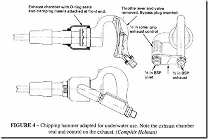
In practice the best way of using tools at depth is to provide an exhaust boss which permits the connection of a hose to take the exhaust air back to the surface where it can be held bouyant at its open end by floats. Some manufacturers provide tools in this form, but often only to special order. Figure 4 shows one such modified tool. An exhaust hose gives the added advantage of improving visibility, but not all the air escapes through the exhaust port- there is plenty of leakage around the shank of the tool bit and from other unsealed joints, so ideally extra sealing is required for these regions. The exhaust hose must be generously sized, otherwise it would cause its own back pressure. Two further points are to be noted when using a return hose. Firstly, the inlet pressure must be higher than the local water pressure otherwise the water would leak into the tool. Secondly the return hose must be sufficiently robust so as not to collapse under external water pressure; conventional pneumatic hose has been found to be unsatisfactory in this application either a wire wound hose (which is heavy and hard to manoeuvre) or a moulded PVC hose should be satisfactory.
Most modern tools as described in earlier chapters incorporate a noise muffler to meet onshore noise regulations, which is their main duty. To find a tool of the more traditional form with an exhaust port, which lends itself to the attachment of an exhaust hose, may Exhaust chamber with O·ring seals and clamping means attached at front end.
not be easy. A special tool may need to be designed and made. The general principles illustrated in Figure 4 should be followed.
An effective way of keeping a tool free from water, when not being used, is to transfer the on/off control from the inlet stem to the exhaust port; the tool is then kept coptinually under pressure and water is unable to get access to the working parts.
When drilling rock or concrete, high pressure water flushing has proved to be more efficient than air flushing. All tools require a hold-down force to keep them applied to the work; this may be difficult under water, so some means of reaction must be available to the operator, probably by anchoring him to the work surface.
Incoming search terms:
- application of hydraulics and pneumatics in marines
- application of pneumatic in marine industry
- application of pneumatics in Marine industry
- Marine Pneumatic Systems mail


