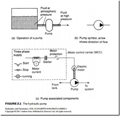
A hydraulic pump (Figure 2.1) takes oil from a tank and delivers it to the rest of the hydraulic circuit. In doing so it raises oil pressure to the required level. The operation of such a pump is illustrated in Figure 2.1a. On hydraulic circuit diagrams a pump is represented by the symbol in Figure 2.1b, with the arrowhead showing the direction of flow.
Hydraulic pumps are generally driven at constant speed by a three-phase AC induction motor rotating at 1500/1000 rpm in the UK (with a 50 Hz supply) and
at 1200/1800 rpm in the USA (with a 60 Hz supply). Often pump and motor are supplied as one combined unit. As an AC motor requires some form of starter, the complete arrangement illustrated in Figure 2.1c is needed.
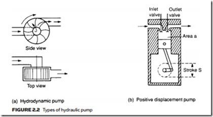
There are two types of pump (for fluids) or compressor (for gases), illus- trated in Figure 2.2. Typical of the first type is the centrifugal pump of Figure 2.2a. Fluid is drawn into the axis of the pump, and flung out to the periphery by centrifugal force. Flow of fluid into the load maintains pressure at the pump exit. Should the pump stop, however, there is a direct route from outlet back to inlet and the pressure rapidly decays away. Fluid leakage will also occur past the vanes, so pump delivery will vary according to outlet pressure. Devices such as that shown in Figure 2.2a are known as hydrodynamic pumps, and are primarily used to shift fluid from one location to another at relatively low pressures. Water pumps are a typical application.
Figure 2.2b shows a simple piston pump called a positive displacement or hydrostatic pump. As the piston is driven down, the inlet valve opens and a vol- ume of fluid (determined by the cross-section area of the piston and the length of stroke) is drawn into the cylinder. Next, the piston is driven up with the inlet valve closed and the outlet valve open, driving the same volume of fluid to the pump outlet.
Should the pump stop, one of the two valves will always be closed, so there is no route for fluid to leak back. Exit pressure is therefore maintained (assum- ing there are no downstream return routes).
More important, though, is the fact that the pump delivers a fixed volume of fluid from inlet to outlet each cycle, regardless of pressure at the outlet port. Unlike the hydrodynamic pump described earlier, a piston pump has no inher- ent maximum pressure determined by pump leakage: if it drives into a dead-end load with no return route (as can easily occur in an inactive hydraulic system with all valves closed) the pressure rises continuously with each pump stroke until either piping or the pump itself fails.
Hydraulic pumps are invariably hydrostatic and, consequently, require some method of controlling system pressure to avoid catastrophic pipe or pump fail- ure. This topic is discussed further in a later section.
A hydraulic pump is specified by the flow rate it delivers, called the dis- placement (usually given in liters min−1, gallons min−1 or liters per rev), and the maximum pressure the pump can withstand. These are normally called the pump capacity (or delivery rate) and the pressure rating.
Pump data sheets specify required drive speed (usually 1500/1000 rpm (50 Hz) or 1800/1200 (60 Hz) corresponding to the common standard speeds of a three-phase induction motor). Pump displacement is directly related to drive speed; at a lower than specified speed, pump displacement is reduced and pump efficiency falls as fluid leakage (called slippage) increases. Pump displacement cannot, on the other hand, be expected to increase by increasing drive speed, as effects such as centrifugal forces, frictional forces and fluid cavitation will drastically reduce service life.
Like any mechanical device, pumps are not 100% efficient. The efficiency of a pump may be specified in two ways. First, volumetric efficiency relates actual volume delivered to the theoretical maximum volume. The simple piston
pump of Figure 2.2b, for example, has a theoretical volume of A s delivered per stroke, but in practice the small overlap when both inlet and outlet valves are closed will reduce the volume slightly.
Second, efficiency may be specified in terms of output hydraulic power and input mechanical (at the drive shaft) or electrical (at the motor terminals) power.
Typical efficiencies for pumps range from around 90% (for cheap gear pumps) to about 98% for high-quality piston pumps. An allowance for pump efficiency needs to be made when specifying pump capacity or choosing a suit- able drive motor.
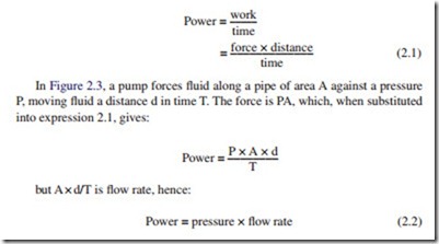
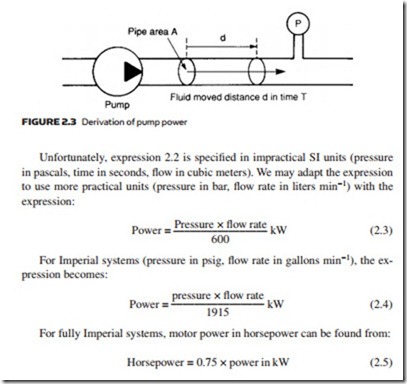
The motor power required to drive a pump is determined by the pump capacity and working pressure. From expression 1.6:
Hydraulic pumps such as that in Figure 2.1 do not require priming because fluid flows, by gravity, into the pump inlet port. Not surprisingly this is called a self-priming pump. Care must be taken with this arrangement to avoid sediment from the tank being drawn into the pump.
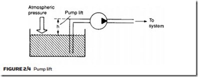
The pump in Figure 2.4 is above the fluid in the tank. The pump creates a negative (less than atmospheric) pressure at its inlet port, causing fluid to be pushed up the inlet pipe by atmospheric pressure. This action creates a fluid lift which is, generally, incorrectly described as arising from pump suction. In real- ity fluid is pushed into the pump.
Maximum pump lift is determined by atmospheric pressure and is given by expressions 1.3 and 1.4. In theory a lift of about 8 m is feasible but, in practice, would be accompanied by undesirable side effects such as cavitation (formation and destructive collapse of bubbles from partial vaporization of fluid). The lift should be as small as possible and around 1 m is a normal practical limit.
Fluid flow in the inlet line always takes place at negative pressure, and a rela- tively low flow velocity is needed to reduce these side effects. The design should aim for a flow velocity of around 1 m s–1. Examination of any hydraulic system will always reveal pump inlet pipes of much larger diameters than outlet pipes.
Incoming search terms:
- https://yandex ru/clck/jsredir?from=yandex ru;search;web;;&text=&etext=1837 5UFBocNgJU3tM9kxhrXpi2soGoEF4BhCk3spE9gtD7y17F5UUsqXOaGEDzzrcrBwIe8KyGDxTzDO9U4k9PItSw 1004581d2d1464f50c497b045ace6c97275d3639&uuid=&state=_BLhILn4SxNIvvL0W45KSic
- hydraulic motor speed regulation
