Air gauging
One important application of compressed air is in air gauging. Although recent develop ments in electronic gauging have in some applications superseded the use of air systems, there are situations in which it retains many advantages. It is a non- contact system, is self centring and self-cleaning. It is now possible, with the use of an air-to-electronic transducer, to combine the benefits of the two systems.
Commercially available equipment is, in the main, confined to bore gauging and in this application it is a very quick and simple technique, capable of identifying taper, ovality and straightness of a bore.
Principles of operation
If the tube A which terminates in thejet J (Figure I) is connected to a source of compressed air held at constant pressure, air will flow through the jet to atmosphere at a constant rate. If now the surfaceS is moved towards the jet, the escape of air will be impeded and the flow will begin to decrease. Continued advancement of the surface will steadily reduce the flow until finally with the surface in contact with the jet, the flow ceases. This simple device is a displacement-flow transducer which permits detection of the movement of the surface by observing the change in air flow.
area flow meter F measures the flow of air through thejet. The flow responds to the change in flow, rising as the flow increases and falling as it decreases. The flowmeter can be graduated in units oflength to give a scale which can be used to measure the displacement of the surfaceS.
It is not, however, essential to measure directly the changes in air flow; these changes can be converted into changes in air pressure by the method shown in Figure 3. A restriction 0, called the control orifice, is introduced between the regulator and thejet, and the air pressure between this restriction and the jet is measured by means of a suitable pressure indicator G. This indicator, shown in Figure 3 in simple diagrammatic form as a pressure gauge, will register a lower pressure when the air flow through thejet increases and a higher pressure when it decreases. As before the scale of the instrument can be graduated in units of length and used for gauging. This arrangement is a displacement pressure transducer. Most commercially available systems are of this type.
These are the basic ideas of air gauging and are simple in concept. What is important is that they can be used to build robust measuring instruments of extremely high accuracy and stability for use in precision engineering. Their magnification, i.e. the ratio of the movement of the indicator (the float in Figure 2 or the pointer in Figure 3) to the movement of the surface which produces it, varies from relatively low (1000) to very high (100000). Magnifications of 10 000 or 20 000 are common and permit accurate inspection of close tolerance components. The true size of the components are obtained and errors of form can be investigated. The air gauging system thus offers advantages over inspection by limit gauging and can, when required, be used for selective assembly of mating components such as glandless spool valves. The gauging jet can be separated from the indicator (flowmeter or pressure indicator) by a suitable hose connection, so that remote reading can be arranged.
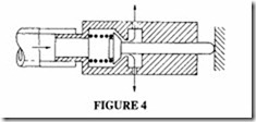
The open jet never makes contact with the work being gauged and may be described as a non-contact gauging element; it is suitable for many applications of air gauging. For others, eg when measuring components which have a rough surface finish or porous surfaces, it is better to use a contact gauging element, comprising a stylus, obturator and jet. This may take several forms, but the principle is shown in Figure4 where it will be seen how the movement of the stylus, which is in contact with the work being gauged, changes
the flow of air through the jet. As in the case of the open jet, the changes of flow can be measured directly by a flowmeter or pressure indicator.
An air gauging system comprises an air gauge unit and a measuring head. The air gauge unit contains both the means to display the measured sizes (or to generate signals based on them), certain other items depending on type; when the variable measured is pressure it will contain the control orifice. The measuring head may contain a single gauging element, either contact or non-contact or two or more such elements. The form of the head and the number of gauging elements used will depend on the type of measurement to be made: length or thickness, internal diameter, external diameter, straightness, squareness etc.
The air supply for the gauging system will usually be drawn from the factory air line, but a local compressor may be employed.
The air gauge must be operated at constant pressure, which requires a pressure regulator, usually incorporated in the air gauge unit. It is essential that the supply pressure is significantly larger than the operating pressure. Systems using flow measurement normally operate at 0.7 bar, whereas systems using pressure measurement are normally from 3 to 7 bar. The air supplied to the unit must be clean and dry and free from oil vapour. The air consumption of a single unit is small (typically about I m3/hour).
The air gauging principle shown in Figures 2 and 3 provides a means for comparing the sizes of like objects, ie it acts as a comparator. As with all comparators it requires standardisation before it can give a true size. Suitable setting standards are therefore required for use with the instrument and are employed in conjunction with simple controls for datum setting and fixing the magnification. In some cases, it is convenient to fix the magnification by using master jets which are substituted for the measuring head.
However precise the instrument used in measuring, it cannot give the correct answer if a poor inspection technique is employed. Change of temperature alters the size of the components being measured; difference of form between the standard and the component or errors in form in the component, may lead to false results.
Typical examples of air gauging
Some of the more direct applications of air gauging are illustrated in Figures 5 and 6, in which the gauging element is represented by an arrow. Figure 5 illustrates a single jet, and Figure 6 multiple jet systems.
One of the features of this system is its flexibility and in consequence its wide field of operation. It is particularly valuable for the simultaneous inspection of several dimen-
sions, and it can conveniently be employed on a machine tool to give measurement during production. Signal retainers and signal inverters can be incorporated; measurements can be converted into electrical signals for automatic control.
Circuit layouts are shown in Figures 7 and 8. Note that the system of Figure 8 incorporates means for regulating the pressure and setting the zero.
A wide range of air plugs are commercially available to measure tapers, ovality, multi diameters, straightness and squareness.
For mechanical contact air gauging, the air plug of Figure 9 can be used. This has pads which contact the measured surface and allows the air to pass through the gap made by the displaced pad.
Air/electronic gauging
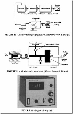
The advantages of air gauging can be combined with an electronic display or for further control purposes. An air/electronic transducer can be incorporated in the system as shown in Figures 10 and 11. The transducer consists of a diaphragm which is sensitive to variations of pressure, whose movement is measured by an electronic probe. The signal can then read by an appropriate display unit, Figure 12.


