Industrial tools
Rotary tools
Most rotary tools employ a vane type motor. This is the simplest and cheapest motor available and it can be made in a small diameter suitable for hand tools. Vane motors have a low inertia which means that they quickly reach maximum speed. Stationary machinery such as hoists and winches tend to employ piston and gear motors which are more robust and can withstand frequent stopping and starting. For high speed die grinders and increasingly for angle grinders, turbine motors are used.
Rotary tools can be divided into:
• grinders and sanders
• drills, tappers and reamers
• screwdrivers, nut runners
• impact wrenches
• impulse wrenches, impulse screwdrivers
• miscellaneous
Grinders and sanders
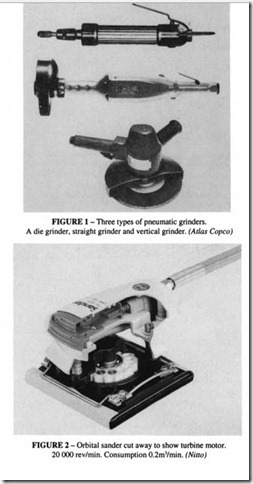
Figure 1 shows three common kinds of grinder. A die grinder uses a small diameter wheel for access to awkward corners and the bottom of dies. Each wheel has a maximum permissible rotary speed which must not be greater than the free speed of the grinder. Attention must be paid to ensuring that the designated speed on the blotter of the wheel cannot under any circumstances be exceeded. In the case of a die grinder, the free speed can be as high as 100 000 r/min, and special precision collets are needed to mount the grinding points. BS 4390 should be referred to for safety requirements; as well as information on safe speeds, it gives design parameters for the construction of safety guards.
The larger sizes of grinders (for wheels greater than about 50 mm diameter) are equipped with a centrifugal governor, which ensures that the free speed is limited to about 10000 r/min. Smaller grinders have to rely on the limitation imposed by the maximum air
flow through the inlet passages. Grinders are supplied with safety guards, which must always be used.
Different shaped wheels are available: cylindrical wheels, cup wheels, depressed centre wheels and cut-off wheels. A variety of special shaped points and tungsten carbide burrs are provided for die grinders.
Rotary sanders are essentially the same as vertical grinders but fitted with a sanding disc in place of a grinding wheel. Orbital sanders driven by a turbine are also available. One example using sanding paper and suitable for fine finishing is shown in Figure 2.
Theory of grinding
Grinding is a process that involves material removal using a succession of cutting edges. As the grains penetrate the material being ground they become worn, and the cutting force increases until they fracture and break out, revealing new and sharp grains. This gives a degree of self-sharpening which depends on the matching between the composition of the wheel and the material being ground. The choice of composition and grain size of the wheel is largely a matter of personal experience and choice. Usually a fine finish is not required of a hand grinder, in contrast to stationary grinders used in a machine shop, so a coarse grit for maximum stock removal is to be preferred.
All grinding wheels have a maximum speed which depends on their composition. BS
The power curve of an ungoverned air motor, on which the design of grinding machines is based, peaks at about half the free speed (refer to the chapter on Air Motors), and this represents the condition at which maximum metal removal is possible. On a governed tool, the peak power point varies from 75 to 90% of the free speed. Most operators are able to judge the best speed fairly accurately with experience. The operator has to press down on the handles, and this force added to the dead weight should be sufficient to realise the ideal working speed.
Pneurop have organised extensive tests on hand-held grinders in assessing the vibration experienced by the operator of the tool (“Investigations on hand-held grinding machines”, obtainable from BCAS). It appears that most of the vibration derives from unbalance in
the wheel, rather than the cutting operation. This unbalance comes either from geometric changes, eg ovality, eccentricity of the centre hole or thickness variation. It may also be induced by uneven wear, or from uneven density in the composition of the wheel; it is possible for a wheel that is initially balanced to develop an unbalance and vice versa. It has been established, contrary to a common belief, that a vibrating tool is not more effective at removing material than a well balanced one. This reinforces the importance of regular dressing of the wheel. The exposure of grinding wheel operators to vibration should be monitored and their time at work restricted.
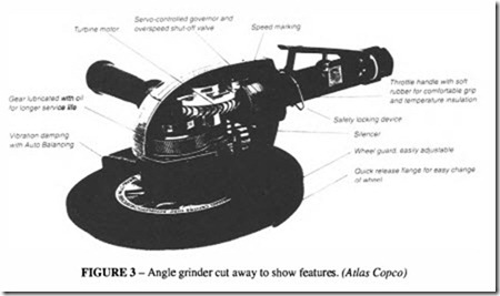
There are now becoming available hand gtinders which incorporate devices which compensate for wheel unbalance. One example is the vertical (angle) grinder of Figure 3 which has a counterbalance mechanism employing bearing balls.
See the chapter on Noise and Vibration for further information.
Screwdrivers and nut runners
A selection of screwdrivers and nut runners is shown in Figure 4. For access to awkward places double angle wrenches are available. Wrenches are provided with square drive to accept standard sockets.
These tools transmit the torque either by direct drive or through a clutch. Direct drive relies on the operator to assess the applied torque, which can be as much as the stall torque of the motor or rather more if account is taken of the inertia of the motor. Clutches are of two broad types- slipping or torque release; the former type slips at the set value of the torque; the latter cuts off the supply of air to the motor. Magnetic clutches are also available. See also Figure 5. These tools have to be reversible, but usually the clutch does not operate when undoing.
Drills, tappers and reamers
These are similar in construction to screw drivers. The larger sizes carry a standard chuck; the smaller sizes employ a collet to grip the drill bit. Tappers can incorporate a reversing mechanism which automatically withdraws the tap at double speed when the cutting operation finishes.
Precision feed drilling
For precision drilling in the aerospace industry and wherever high quality performance is required, a variety of controlled feed mechanisms are available. The following are typical examples:
I. The controlled feed drill has an automatic feed/drill/retract cycle, all operated pneumatically on a hand held tool. The complete cycle is initiated by depressing the trigger. Hydraulic damping controls the feed rate to minimise burring on break through, and the trigger can be locked to allow simultaneous use of more than one unit.
2. The automatic feed drill is similar, but in this case the cycle is initiated by touch of a button and allows for remote start/stop signals, ideal for robotic or special purpose machine applications.
3. Variable feed drills combine power feed with manual feed. The manual feed allows for rapid advance and retraction, and for such applications as swarf clearance when deep hole drilling.
4. Rack feed drills rely on manual feed and retraction, although automatic stop and start of the motor is possible at any point in the stroke.
Combination of air and electric motors for special applications are also available- it is possible to have air feed combined with an electric drill, and also both feed and drilling performed electrically.
Impact wrenches
These are rotary vane motors with an additional rotary impact mechanism to impart a blow as the resistance increases (Figure 6). Impact wrenches are available to apply a torque of up to 100 000 Nm or more with an output drive of31 in. The motor first runs freely until
the nut offers resistance to the torque, whereupon the impact mechanism comes into play to assist further tightening. It is possible to exert high values of torque with small reaction on the operator. Some types have an adjustable torque setting, ensuring that the tension in the bolt is not exceeded. Although the torque setting is unaffected by changes in air pressure, unless the available air pressure is 6 bar or greater the maximum setting of the torque may not be reached.
Various types of torque control are available, according to the manufacturer. Some have a device which cuts off the air supply when the torque setting is reached; some have a built in timer which shuts off the air after a certain time; some have an adjustable restriction which limits the air supply. The firsttypeis more accurate, but they all need to be calibrated on the joint to be tightened, which makes them more suitable for production runs than for the occasional tightening operation. Devices which work by cutting off the supply pressure rely on an ability to sense the amount of rebound off the tightened nut, followed by triggering a cut-off valve. With this method, the response depends on the stiffness of the joint; some tools work better with a stiff joint, some are better for a flexible joint.
For accurate torque settings, torque bars can be used. These are graduated extension bars, inserted between the wrench and socket. two kinds are available: adjustable and non adjustable. They have a calibrated flexibility which is able to trigger a shut-off device when the torque is reached
Impulse tools
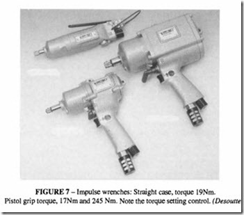
These represent a new development, which for many purposes are replacing impact wrenches, particularly for smaller sizes of bolt (for a torque range up to about 280 Nm and
of metallic impact, an impulse is applied to the output shaft of the tool through a rotating, cam operated, hydraulic piston unit. This results in high speed rundown, much quieter operation, repeatable torque settings and low vibratory reaction on the operator. The absence of metallic impact in the tool means that the service life is likely to be longer than for an impact wrench; a factor of 10x has been quoted, but this will depend on the particular design.
As the impulse unit rotates and the cams engage every 360°, a pulse of energy is transmitted to the output shaft, increasing the fastener torque each time the cams engage. The torque is set by a control knob on the body of the tool.
These tools also incorporate a shut off mechanism which acts to divert the energy of the tool and restrict the supply of air when the resistance of the bolt reaches the torque setting.
Considerations of joint tightness
Although the use of a calibrated torque wrench to control the degree of tightening of a bolted joint is an advance over relying on the feel of the operator, it is not as reliable as a method which directly measures the tension in the bolt. Friction is the dominating influence in trying to correlate the torque with the bolt tension. The coefficient of friction is not easily determined: it varies with the amount oflubricant present, the condition of the mating surfaces and variation in the geometry of the joint. A high degree of accuracy in the applied torque is unlikely to decrease the inherent scatter in the bolt tension values. Two methods have been developed to overcome this problem.
The first method is known as Angle-controlled Tightening. It is a method of indirect elongation measurement avoiding the practical difficulties inherent in trying to assess the total bolt stretch from head to point. Angle-controlled tightening measures the movement of the nut relative to the clamped component after the mating surfaces are fully seated. The stretch of the bolt and the tension in it can be calculated from the angular movement of the nut and the pitch of the thread.
A plot of torque versus deflection would show a distinct knee in the curve, at the point where the clamping action changed from bringing the surfaces together to stretching the bolt, and it is from this point that the angular movement is measured.
Practical experience in the use of this method indicates that high precision is obtained only if the bolt is tightened beyond its yield point, which is satisfactory in many applications but in others, as for example in joints where the clamping length is short or where the material is brittle, the bolt may be overloaded. The method is unsuitable when bolts experience a working tensile load which adds to the pre-load. Bolts which have been stressed into the plastic region cannot be reused.
A second, more accurate method, known as Gradient-controlled Tightening has been developed. This method, instead of measuring the angle alone, measures both torque and angle and calculates the slope of the torque/angle curve. As soon as this slope reaches the yield point, the air supply is cut off. This technique is only suitable for use on a production line in conjunction with the appropriate electronic analysis equipment; however for less sophisticated applications a portable calibrated torque wrench is available which measures the gradient and can be used to calibrate a power driven wrench and for quality control.
Percussive tools
Percussive industrial tools include:
• chipping hammers
• scaling hammers
• rivetters
• sand rammers
Chipping hammers
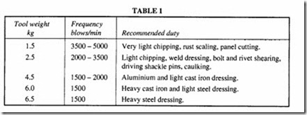
Chipping hammers are percussive tools used for a wide range of industrial purposes:
• removal of welding slag and rust
• dressing castings
• chamfering steel plate for weld preparation
• bolt and rivet shearing
Chipping hammers of a traditional design produce high levels of vibration, and operators who spend most of their working time using one for foundry fettling or some other continuous operation should be monitored for signs of vibration injury (see chapter on Vibration Exposure).
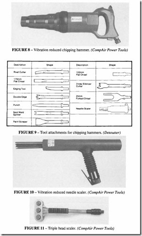
Figure 8shows an example of a modern vibration reduced chipping hammer. The design of this tool has succeeded in reducing the vibration level when compared with a conventional tool (a claimed reduction from a weighted vibration of I 0.5 m/s2 down to 2.1 m/s2).
Chipping hammer chisels are made in a wide choice of shapes to suit different purposes, Figure 9. Shanks can be hexagonal or round, according to manufacturer’s choice; chisels are not necessarily interchangeable between manufacturers, although BS 673 specifies standard dimensions which most manufacturers follow.
Some of the hammers are provided with a boss on the handles for attachment of an
exhaust hose which can be led away to a silencer. It should be borne in mind, when using a silencer, that it may make the tool rather more awkward to handle and may not significantly reduce the noise level, particularly ifmostofthe noise comes from the actual process (drumming of the panel or ringing of the casting).
Scalers
These are similar to light chipping hammers, Figure 10. They are specially designed to remove scale and rust, and for surface preparation. They are available either with a conventional chisel bit or with a bunch of hard spring steel or beryllium copper needles suitable for negotiating awkward shapes.
Figure II illustrates another type of tool designed primarily for surface dressing of stone and concrete.
