Air movers
Introduction
The air mover is at the heart of the pneumatic conveying system, and the success of the entire system rests on correctly specifying the duty of the air mover. The specification is in terms of the volumetric flow rate of free air required, and the pressure at which it must be delivered. The values of these two parameters are primarily dependent upon the material to be conveyed, its flow rate and the conveying distance, and this is considered in Chapter 9. The choice of an air mover to supply the air at the desired flow rate and pressure is equally important, and there is a wide range of machines that are potentially capable of meeting the duty.
Not all air movers are ideally suited to pneumatic conveying, however, and so the operating characteristics must be understood and interpreted. Plant air may be avail- able, but it may not be economical to use it for pneumatic conveying. Some air movers have limitations, and some are more suited as exhausters than compressors, and so the correct choice must be made for vacuum and positive pressure duties.
There are also many peripheral issues associated with the supply of air for pneumatic conveying systems that need to be considered, in addition to the basic hardware. Power requirements for pneumatic conveying can be very high, particularly if it is required to convey a material at a high flow rate over a long distance, and so a first order approximation is presented to allow reasonably reliable estimates to be made early in the selection process.
With most compressors the air is delivered at a high temperature, but this may have to be cooled if high temperature air is not suitable for conveying the material. When compressed air is cooled to ambient temperature, however, it often becomes saturated with water, and this may cause problems. In addition, many compressors do not deliver oil free air.
Types of air mover
Air movers available for pneumatic conveying applications range from fans and blowers, producing high volumetric flow rates at relatively low pressures, to positive dis- placement compressors, usually reciprocating or rotary screw machines, capable of producing the higher pressures required for long distance or dense phase conveying systems. The main features of some air movers typically employed for pneumatic conveying duties are outlined, in particular the operating characteristics.
The basic types of air mover are categorized in a chart of compressor types in Figure 6.1 and their approximate performance coverage, in terms of delivery pressure and volumetric flow rate of free air delivered, are illustrated in Figure 6.2. It should be emphasized that Figure 6.2 is intended only to give a guide to the range of operation of different types of machine. In most cases there are substantial overlaps in their performance coverage. In particular, the reciprocating compressor is available in a very extensive range of sizes and types, and models could be found to satisfy almost any operating conditions shown on Figure 6.2. Many compressors are capable of being staged to deliver air at higher pressures and so this will also be considered.
Aerodynamic compressors
For high pressure duties centrifugal compressors, and especially the multiple stage axial flow machines, are normally manufactured only in large sizes, handling very high volumetric flow rates, and so they rarely find application to pneumatic conveying installations. Axial flow compressors are widely used in aircraft engines. Multiple stage centrifugal compressors are also capable of delivering high flow rates at high pressure, and are often used to provide the air for testing aircraft engines in wind tunnels. Single stage machines find widespread use for short distance dilute phase systems, as these provide high volumetric flow rates at low pressures.
Fans
In pneumatic conveying applications, fans used are normally of the radial, flat bladed type. Fans are widely used on short distance, dilute phase systems, where the chance of blocking the line is small. Fans may be used on both positive and negative pressure systems and also on combined ‘suck–blow’ systems, where, with light or fluffy, non- abrasive materials, it is sometimes possible to convey the material through the fan itself, which is not a possibility with most of the positive displacement machines.
On vacuum duties they are often used for cleaning operations. With waste and stringy materials, such as straw and paper, plastic, film and textile trim, it is even possible to sharpen the blades of the fan so that they will cut or chop the material into pieces as it passes through the fan. Fans, however, are not suitable for higher pressure and heavy duty operation. This is because their operating characteristics are generally not satisfactory for the duty or application.
Constant speed characteristics
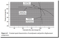
The main problem with fans is that they suffer from the disadvantage that the air flow rate is very dependent upon the conveying line pressure drop. The constant speed oper- ating characteristic tends to flatten out at high operating pressure. This is a fundamental operating characteristic for pneumatic conveying, and so this class of compressor cannot be used reliably. With a compressor having this type of operating characteristic, it means that if the solids feed rate to the system should become excessive for any reason, causing the pressure drop to increase significantly, the air flow rate may become so low that the material will drop out of suspension, with the risk of blocking the line.
This is particularly a problem in dilute phase suspension flow systems where the conveying air velocity is relatively high. The mean value of conveying air velocity in a dilute phase system is typically about 20 m/s, and so for a 100 m long pipeline, for example, it will only take about 5 s for the air to traverse the entire length of the pipe- line. A short surge in feed rate, therefore, can quickly have a significant effect on the pressure required. If the conveying air velocity falls below the minimum value as a consequence, the pipeline can become blocked in a short space of time. Positive dis- placement machines, for which the volumetric flow rate is largely independent of the discharge pressure, are less likely to cause this type of system failure. This point is illustrated in Figure 6.3.
In order to convey materials reliably in pneumatic conveying systems, a minimum value of conveying air velocity must be maintained. For dilute phase conveying systems this minimum velocity is typically of the order of 15 m/s, and if it drops by more than about 10 or 20 per cent the pipeline is likely to block. A small surge in the feed rate into a pipeline of only 10 per cent would cause a corresponding increase in pressure
demand, and with either an axial flow or a radial flow machine, the reduction in the volumetric flow rate of the air would probably result in pipeline blockage.
Regenerative blowers
The performance curves for regenerative (side-channel) blowers are generally better than those of the aerodynamic compressors shown in Figure 6.3, but they are not as good as those for positive displacement machines. There is a natural tendency to oper- ate a compressor at a pressure close to its maximum rating, but it is generally in this area that the operating characteristics deteriorate.
Since the cost of the air mover will represent a significant proportion of the total sys- tem cost, this is an area where potential savings can be made. Particular care should be taken if regenerative blowers are to be considered, therefore, and it is essential that the operating characteristics of the machine are related to the extreme requirements of the system. A beneficial feature claimed for these blowers is that they are less sensitive than most positive displacement machines to erosive wear from dust laden air.
Positive displacement compressors
The constant speed operating characteristic for positive displacement machines, shown on Figure 6.3, provides a basis on which the design of heavy duty conveying systems can be reliably based. A pressure surge in the conveying system will result in only a small decrease in the air flow rate delivered by the compressor, and this can be incorporated into the safety margins for the system. A pressure surge, of course, will additionally cause a reduction in air velocity because of the compressibility effects, and this must also be catered for in such safety margins. With a positive displacement compressor,
however, the percentage reduction in conveying air velocity due to the constant speed characteristic will be no more than that caused by the compressibility effect.
In the classification of compressors presented in Figure 6.1, five different types of positive displacement compressor are included. The constant speed-operating characteristic of each of these is similar to that shown on Figure 6.3. A particular feature of most of these machines is that very fine operating clearances are generally maintained between rotating parts. As a result there is no possibility of the conveyed material pass- ing through the compressor, with the limited exception of the liquid ring machine, as it can with a fan. Indeed, if the material being conveyed is abrasive, even dust must be prevented from entering most machines or they will suffer severe damage.
Roots (positive displacement) type blowers
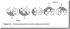
In 1854 Roots invented the original rotary positive displacement blower. They are now widely used on pneumatic conveying applications where the operating pressure does not exceed about 1 bar gauge. Roots type, or positive displacement, blowers are prob- ably the most commonly used type of compressor for dilute phase conveying systems. The principle of the blower is illustrated in Figure 6.4.
The blower provides an ideal match, in terms of pressure capability, with the conventional low pressure rotary valve, and this is a typical working combination on many plants operating in industry. Positive displacement blowers are generally bi-rotational, so that they can be used as vacuum pumps, or exhausters, as well as compressors. They are normally available in sizes handling up to about 500 m3/min, although some manufacturers quote 1500 m3/min.
As will be seen from Figure 6.4, twin rotors are mounted on parallel shafts within a casing, and they rotate in opposite directions. As the rotors turn, air is drawn into the spaces between the rotors and the casing wall, and is transported from the inlet to the outlet without compression. As the outlet port is reached, compression takes place when the air in the delivery pressure pipe flows back and meets the trapped air.
Due to this shock compression the thermodynamic efficiency of the machine is a little lower than that of other compressors, and is one of the reasons why these simple compressors are only used for low pressure applications. In order to reduce the pulsation level, and the noise, three lobed rotors, as well as twisted rotors, have been introduced, and they now operate at very much higher speeds.
The maximum value of compression ratio with these machines is generally 2:1 when operating oil free. This means that for blowing, the maximum delivery pressure is about 1.0 bag gauge, and for exhausting, the maximum vacuum is about 0.5 bar. For combined vacuum and blowing duties these pressures will naturally be much lower, and are typically between 0.7 bar absolute (0.3 bar of vacuum) and 1.4 bar absolute (0.4 bar gauge), as a maximum. Even with a lubricated machine little improvement on this operating range can be achieved for suck–blow conveying systems.
Compressors
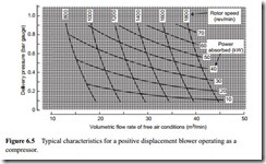
Gears control the relative position of the two impellers to each other, and maintain very small but definite clearances. This allows operation without lubrication being required inside the air casing. The performance of the machine would be enhanced with lubrication, with a delivery pressure capability of about 1.25 bar gauge, but oil free air is a general requirement of these machines. Double shaft seals with ventilated air gaps are generally provided in order to ensure that the compressed air is oil free. Typical blower characteristics are shown in Figure 6.5 for a positive displacement blower operating as a compressor.
A further development with this type of machine is to operate at very much higher speeds than those indicated on Figure 6.5. Operating speeds for new machines are now approximately double those indicated on Figure 6.5, but the slope of the constant speed and power absorbed lines remain exactly the same. With an improvement in materials of manufacture, greater accuracy of machining, and higher speed operation, blowers have been developed into a more compact machine. The thermodynamic efficiency is improved, and as a result the operating temperature is lowered, and there is a corresponding reduction in power requirements.
Manufacturers of positive displacement blowers rarely present the operating characteristics in the form shown in Figure 6.5, but a plot of this kind does illustrate very clearly the constant speed characteristics of the machine. It is also very useful in terms
of making changes in performance across the range of rotor speeds and operating duties that the particular model covers. Lines of constant power requirement are particularly useful as these will indicate whether the changes can be achieved with an existing drive.
Exhausters
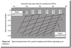
Performance characteristics for a similar positive displacement blower operating as an exhauster are presented in Figure 6.6.
Pressure capability
The limit on the compression ratio of 2:1 for these machines, when running dry, is essentially dictated by the operating temperature. At pressures higher than 1 bar gauge, and vacuums below 0.5 bar, the discharge air temperatures generated can result in casing and impeller distortion. Oil lubrication can extend this range of operation for, apart from lubricating the machine, it will have a cooling effect, but it does mean that an oil filter and an oil cooler will have to be added.
Water injection will have a very significant effect on the cooling of the air, but this is not always desirable. Water or forced air cooling of the machine can also be employed, as this will allow the higher compression air temperatures to be achieved, while limiting the operating temperature of the machine itself. By these means positive displacement blowers are available that will deliver air at pressures of up to 2 bar gauge and at vacuums down to 0.65 bar with a single stage.
Staging
As with most aerodynamic and positive displacement machines, staging is also possible with positive displacement blowers, although it is probably less common, and is generally Volumetric flow rate of free air conditions (m3/min)
limited to a maximum of two machines in series. For blowing, the compression ratio is usually limited to about 1.7 for each machine, for oil free operation, and so a delivery pressure close to 2 bar gauge can be achieved by this means. With lubricated machines the compression ratio can be increased to about 1.95, which means that a delivery pressure of 2.8 bar gauge is a possibility.
If blowers are to be operated in series the air at outlet from the first stage must be cooled before the second stage. Although heat exchangers are generally used for this purpose, water sprays can also be used. Evaporation of water can have a very significant cooling effect, because of the very high enthalpy of evaporation, hfg, which is typically over 2400 kJ/kg for water, and so the mass flow rate of water for this purpose would only need to be about 2 per cent of the air flow rate. Consideration, of course, must be given to any subsequent problems with the conveyed material and condensation.
Sliding vane rotary compressors
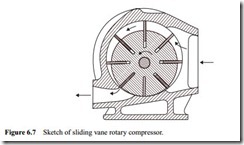
For medium and high pressure systems the sliding vane type of rotary compressor is well suited. These generally produce a smoother flow of air at a higher pressure than the positive displacement blower, and a single stage machine is capable of delivering in excess of 50 m3/min at a maximum pressure of about 4 bar. Significantly higher operating pressures may be obtained from two stage machines. Oil injection also permits higher work- ing pressures (up to about 10 bar), but this type of machine is generally not available in capacities greater than about 6 m3/min.
Figure 6.7 illustrates the operating principle of a simple single stage sliding vane compressor. It is a single rotor device, with the rotor eccentric to the casing. Compression, as will be seen from Figure 6.7, occurs within the machine, unlike the positive displacement blower, and so the air is delivered without such marked pulsations. It will be seen that the machine will operate equally well as an exhauster for vacuum conveying duties.
It should be noted that some form of cooling is essential since quite high temperatures can be reached as a result of the combined effect of the vanes rubbing against the casing and the compression of the air between the rotor and the casing. The cooling
may be by water circulated through an external jacket, or by the injection of oil directly into the air stream just after the beginning of compression.
As mentioned previously, the direct injection of oil into the machine does permit higher working pressures, but an efficient oil separation system does add to the cost of the plant.
Liquid ring compressors
Most of the air movers described previously, or suitable variations of these, can be used on negative pressure conveying systems. However, the most commonly used are positive displacement blowers, operating as exhausters, which are capable typically of holding a continuous vacuum of about 400 mmHg gauge (360 mmHg absolute). Higher vacuums can be maintained by positive displacement blowers fitted with water injection, but it would be more usual to employ a liquid ring vacuum pump which can reach 600 mmHg gauge (160 mmHg absolute) in a single stage, and over 700 mmHg in two stages.
Liquid ring vacuum pumps having capabilities from about 1 m3/min up to 70 m3/min are available. The liquid ring compressor was developed around 1905 from a self- priming rotary water pump, first built in 1817. As a compressor it is used for applications up to about 4 bar. This type of compressor, however, is relatively inefficient and so is mainly used for low pressure applications, more generally as vacuum pumps. A particular advantage of the machine is that it produces oil free air. A typical form of liquid ring compressor is illustrated in Figure 6.8.
As with the sliding vane rotary compressor, this is also a single rotor machine in which the rotor is eccentric to the casing. As the impeller rotates, the service liquid (usually water) is thrown outwards to form a stable ring concentric with the pump casing. As the impeller itself is eccentric to the casing, the spaces between the impeller blades and the liquid ring vary in size so that air entering these spaces from the suction port is trapped and compressed before being discharged through the outlet port. Compression, therefore, occurs within the machine, as with the sliding vane compressor.
The liquid ring also performs the useful functions of cooling the compressed air and washing out small quantities of entrained dust. The tolerance of the machine to dust is a particular advantage in vacuum conveying systems and is, therefore, widely used in this application.
Rotary screw compressors
A relatively recent innovation for medium to high pressure operation is the helical lobe rotary, or Lysholm, screw compressor. The rotary screw compressor was patented in 1878, but in a form similar to the Roots blower, that is, without internal compression. The mathematical laws for obtaining compression were developed by the Swedish engineer, A. Lysholm in the 1930s.
In 1958 rotor profiles giving a high efficiency were developed but these require oil injection into the compression chamber to reduce internal air leakage. The oil helps to cool the air during compression but, as with oil injected sliding vane machines, it is generally necessary to remove the oil from the compressed air. With large compres- sors the injection, separation and filtration equipment can represent a substantial pro- portion of the plant cost. In 1967 a much improved rotor profile was developed which allowed rolling motion between the rotor flanks with reduced air leakage, without the need for oil injection.
The machine consists essentially of male and female intermeshing rotors mounted on parallel shafts. Inlet and outlet ports are at opposite ends of the compressor. Air entering one of the cavities in the female rotor becomes trapped by a male lobe, and as the rotors turn, this trapped air is compressed and moved towards the discharge end. Continuing rotation of the lobes causes the discharge opening to be uncovered so that the trapped air, now at minimum volume, is released into the discharge line.
Screw compressors are manufactured with capacities ranging from 4 to 700 m3/min.
With oil injection they can develop maximum pressures of about 9 bar. Dry machines can reach 11 bar with two stages, and about 4 bar with a single stage. As these machines are generally free from pressure pulsations it is not usually necessary to operate with an air receiver, and they do not require special foundations for mounting.
Reciprocating compressors
The familiar reciprocating compressor, until recent years, was probably the most widely used machine for providing high pressure air for pneumatic conveying systems, but the screw compressor has been a serious competitor where large flow rates are required. Reciprocating compressors are available as single cylinder machines, or with multiple cylinders arranged to give one or more stages of compression. Reciprocating compressors probably have the best thermodynamic efficiency of any air mover.
Where it is essential that there should be no material contamination with oil, reciprocating compressors can be provided with carbon filled polytetrafluoroethylene (ptfe) rings, which eliminate the need for oil in cylinder lubrication, and hence additional separation equipment. A compressor of this type could thus be found to suit almost any pneumatic conveying application in the medium to high pressure range. Even the disadvantage of a pulsating air flow, usually associated with reciprocating machines, can be overcome by selecting one of the modern, small mobile cylinder compressors, such as that in which seven pairs of radially disposed opposing pistons are made to reciprocate by the motion of a centrally placed wobble plate.
Staging
Arranging two or more compressors in series, in order to achieve higher delivery pressures, is possible with most types of compressor, as mentioned earlier with respect to the staging of positive displacement blowers. To improve the efficiency of compression it is usual to cool the air between the stages. Due to the high delivery temperature of air from compressors, which is considered in detail in Section of 6.3.1, this cooling is essential.
The lower volumetric flow rate of the air, as a result of the increase in pressure, and the reduction in temperature, will mean that the size of the next compression stage can be reduced, apart from improving conditions with regard to lubrication as a result of the lower air temperature. Inter-cooling by means of an air blast, or a water-based heat exchanger, are the normal means of cooling the air between stages.
With regard to the staging of positive displacement blowers, considered above, it was mentioned that water sprays could also be used. Some compressors, however, are susceptible to damage by water drops and so it is generally recommended that the air between stages should not be cooled to a temperature below that of the prevailing dew point. This aspect of air requirements is considered in some detail in Chapter 25 on ‘Moisture and condensation’. The elimination of water between stages will also minimize the problems caused by the possible rusting of materials in this area.
Incoming search terms:
- air movers whisle type
- Air Mover
- different compressors characteristics
- pnematic blower types air mover compressor
- types of air movers

