Fundamental principles
Industrial prime movers
Most industrial processes require objects or substances to be moved from one location to another, or a force to be applied to hold, shape or compress a product. Such activities are performed by Prime Movers; the workhorses of manufacturing industries.
In many locations all prime movers are electrical. Rotary motions can be provided by simple motors, and linear motion can be obtained from rotary motion by devices such as screw jacks or rack and pinions. Where a pure force or a short linear stroke is required a solenoid may be used (although there are limits to the force that can be obtained by this means).
Electrical devices are not, however, the only means of providing prime movers. Enclosed fluids (both liquids and gases) can also be used to convey energy from one location to another and, conse quently, to produce rotary or linear motion or apply a force. Fluid based systems using liquids as transmission media are called hydraulic systems (from the Greek words hydra for water and autos for a pipe; descriptions which imply fluids are water although oils are more commonly used). Gas-based systems are called Pneumatic systems (from the Greek pneumn for wind or breath). The most common gas is simply compressed air. although nitrogen is occa sionally used.
The main advantages and disadvantages of pneumatic or hydraulic systems both arise out of the different characteristics of low density compressible gases and (relatively) high density incompressible liquids. A pneumatic system, for example, tends to have a ‘softer’ action than a hydraulic system which can be prone to producing noisy and wear inducing shocks in the piping. A liquid-based hydraulic system, however, can operate at far higher pressures than a pneumatic system and, consequently, can be used to provide very large forces.
To compare the various advantages and disadvantages of electrical pneumatic and hydraulic systems, the following three sections consider how a simple lifting task could be handled by each.
A brief system comparison
The task considered is how to lift a load by a distance of about 500 mm. Such tasks are common in manufacturing industries.
With an electrical system we have three basic choices; a solenoid, a DC motor or the ubiquitous workhorse of industry, the AC induction motor. Of these, the solenoid produces a linear stroke directly but its stroke is normally limited to a maximum distance of around 100 mm.
Both DC and AC motors are rotary devices and their out puts need to be converted to linear motion by mechanical devices such as wormscrews or rack and pinions. This presents no real problems; commercial devices are available comprising motor and screw.
The choice of motor depends largely on the speed control requirements. A DC motor fitted with a tacho and driven by a thyristor drive can give excellent speed control, but has high main tenance requirements for brushes and commutator.
An AC motor is virtually maintenance free, but is essentially a fixed speed device (with speed being determined by number of poles and the supply frequency). Speed can be adjusted with a vari able frequency drive, but care needs to be taken to avoid overheating as most motors are cooled by an internal fan connected directly to the motor shaft. We will assume a fixed speed raise/lower is required, so an AC motor driving a screwjack would seem to be the logical choice.
Neither type of motor can be allowed to stall against an end of travel stop, (this is not quite true; specially-designed DC motors, featuring good current control on a thyristor drive together with an external cooling fan, can be allowed to stall), so end of travel limits are needed to stop the drive.
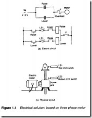
We have thus ended up with the system shown in Figure 1.1 comprising a mechanical jack driven by an AC motor controlled by a reversing starter. Auxiliary equipment comprises two limit switches, and a motor overload protection device. There is no practical load limitation provided screw/gearbox ratio, motor size and con tactorrating are correctly calculated.
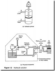
A solution along hydraulic lines is shown in Figure 1.2. A hydraulic linear actuator suitable for this application is the ram, shown schematically in Figure 1.2a. This consists of a movable piston con nected directly to the output shaft. If fluid is pumped into pipe A the piston will move up and the shaft will extend; if fluid is pumped into pipe B, the shaft will retract. Obviously some method of retrieving fluid from the non-pressurised side of the piston must be incorporated.
The maximum force available from the cylinder depends on fluid pressure and cross sectional area of the piston. This is discussed further in a later section but, as an example, a typical hydraulic pressure of 150 bar will lift 150 kg cm-2 of piston area. A load of 2000 kg could thus be lifted by a 4.2cm diameter piston.
A suitable hydraulic system is shown in Figure 1.2b. The system requires a liquid fluid to operate; expensive and messy and, conse quently, the piping must act as a closed loop, with fluid transferred from a storage tank to one side of the piston, and returned from the other side of the piston to the tank. Fluid is drawn from the tank by a pump which produces fluid flow at the required 150 bar. Such high pressure pumps, however, cannot operate into a dead-end load as they deliver constant volumes of fluid from input to output ports for each revolution of the pump shaft. With a dead-end load, fluid pressure rises indefinitely, until a pipe or the pump itself fails. Some form of pressure regulation, as shown, is therefore required to spill excess fluid back to the tank.
Cylinder movement is controlled by a three position changeover valve. To extend the cylinder, port A is connected to the pressure line and port B to the tank. To reverse the motion, port B is connected to the pressure line and port A to the tank. In its centre posi tion the valve locks the fluid into the cylinder (thereby holding it in position) and dead-ends the fluid lines (causing all the pump output fluid to return to the tank via the pressure regulator).
There are a few auxiliary points worthy of comment. First, speed control is easily achieved by regulating the volume flow rate to the cylinder (discussed in a later section). Precise control at low speeds is one of the main advantages of hydraulic systems.
Second, travel limits are determined by the cylinder stroke and cylinders, generally, can be allowed to stall at the ends of travel so no overtravel protection is required.
Third, the pump needs to be turned by an external power source; almost certainly an AC induction motor which, in tum, requires a motor starter and overload protection.
Fourth, hydraulic fluid needs to be very clean, hence a filter is needed (shown in Figure 1.2b) to remove dirt particles before the fluid passes from the tank to the pump.
One final point worth mentioning is that leaks of fluid from the system are unsightly, slippery (hence hazardous) and environmen tally very undesirable A major failure can be catastrophic.
At first sight Figure 1.2b appears inordinately complicated com pared with the electrical system of Figure 1.1, but it should be remembered all parts enclosed in the broken-lined box in Figure 1.2 are common to an area of plant and not usually devoted to just one motion as we have drawn.
A pneumatic system
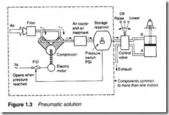
Figure 1.3 shows the components of a pneumatic system. The basic actuator is again a cylinder, with maximum force on the shaft being determined by air pressure and piston cross sectional area. Operating pressures in pneumatic systems are generally much lower than those in a hydraulic systems; 10 bar being typical which will lift 10 kg cm-2 of piston area, so a 16 em diameter piston is required to lift the 2000 kg load specified in the previous section. Pneumatic systems therefore require larger actuators than hydraulic systems for the same load.
The valve delivering air to the cylinder operates in a similar way to its hydraulic equivalent. One notable difference arises out of the simple fact that air is free; return air is simply vented to atmosphere.
Air is drawn from the atmosphere via an air filter and raised to required pressure by an air compressor (usually driven by an AC motor). The air temperature is raised considerably by this compressor. Air also contains a significant amount of water vapour. Before the air can be used it must be cooled, and this results in the formation of condensation So, the air compressor must be followed by a cooler and air treatment unit.
Compressibility of a gas makes it necessary to store a volume of pressurised gas in a reservoir, to be drawn on by the load. Without this reservoir, a slow exponential rise of pressure results in a similar slow cylinder movement when the valve is first opened. The air treatment unit is thus followed by an air reservoir.
Hydraulic systems require a pressure regulator to spill excess fluid back to the tank, but pressure control in a hydraulic system is much simpler. A pressure switch, fitted to the air reservoir, starts the compressor motor when pressure falls and stops it again when pressure reaches the required level.
The general impression is again one of complexity, but units in the broken-lined box are again common to one plant or even a whole site. Many factories produce compressed air at one central station and distribute an air ring main to all places on the site in a similar way to other services such as electricity, water or gas.
Table 1.1 gives superficial comparisons of the various systems dis cussed in the previous sections.


