Design Fundamentals
There are certain design fundamentals that should be clearly understood before attempting to analyze the operating condition of reciprocating compressors. The fun damentals include the following.
Frame and Running Gear
Two basic factors guide the designer of the frame and running gear. First is the maxi mum horsepower to be transmitted through the shaft and running gear to the cylinder pistons; second is the load imposed on the frame parts by the pressure differential between the two sides of each piston. The latter is often called pin load because this full force is directly exerted on the crosshead and crankpin. These two factors deter mine the size of bearings, connecting rods, frame, and bolts that must be used throughout the compressor and in its support structure.
Cylinder Design
The efficiency of compression is entirely dependent upon the design of the cylinder and its valves. Unless the valve area is sufficient to allow gas to enter and leave the cylinder without undue restriction, efficiency cannot be high. Valve placement for free flow of gas in and out of the cylinder is also important.
The method of cylinder cooling must be consistent with the service intended, since both efficiency and maintenance are influenced by the degree of cooling during com pression. The cylinders and all its parts must be designed to withstand the maximum pressure to which it will be exposed, using those materials that will economically give the proper strength and the longest service under design conditions.
Inlet and Discharge Valves
Compressor valves are devices placed in each cylinder to permit one-way flow of gas either into or out of the cylinder. There must be one or more for inlet and discharge in each compression chamber.
Each valve must open and close once for each revolution of the crankshaft. The valves in a compressor operating at 700 rpm for 8 hours per day and 250 days per year will have opened and closed 42,000 times per hour, 336,000 times per day, or 84 million times in a year.
They have less than 1/10 of a second to open, let the gas pass through, and close. They must do this with a minimum of resistance or power will be wasted. They must have small clearance space or there will be excessive re-expansion during the suction stroke and reduced volumetric efficiency. They must be tight under severe pressure and temperature conditions. Finally, they must be durable under many kinds of abuse.
Types of Valves
There are four basic valve designs used in various compressors. These are finger, channel, leaf, and annular ring. Within each class there may be variations in design details depending upon operating speed and size of valve required.
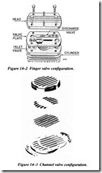
Finger. Figure 14-2 shows a typical finger valve before assembly. These valves are used for smaller, air-cooled compressors. One end of the finger is fixed and the oppo site end lifts when the valve opens.
Channel . The channel valve (Figure 14-3) is widely used in mid-sized to large compressors . This type of valve uses a series of separate stainless steel channels as valves. This is a cushioned valve as explained in the figure , which adds greatly to its life.
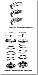
Leaf. The leaf valve has a configuration somewhat like the channel. It is fiat strip steel that opens against an arched stop plate so that the valve flexes with maximum lift only at its center. The valve (Figure 14-4) is its own spring.
Annular ring. Figure 14-5 illustrates both inlet and discharge explosion drawings of a typical annular ring valve. The example has a single ring. Larger sizes may have two or three rings. Some designs have the concentric rings tied into a single piece by bridges. The valve shown was the first cushioned valve built.
The springs and valve move into a recess in the stop plate as the valve opens. Gas trapped in the recess acts as a cushion and prevents slamming. This eliminates a major source of valve and spring breakage.
Cylinder Cooling
Heat in a cylinder is produced by the work of compression, plus the friction of the pis ton and piston rings on the cylinder wall and of the rod packing on the rod. Heat can be considerable, particularly when moderate and high compression ratios are involved. Undesirably high operating temperatures can be developed.
Most compressors use some method of dissipating a portion of this heat, thus reduc ing both cylinder wall temperature and final gas temperature. There are several advan tages in cylinder cooling, at least, some of which apply to all but exceptional cases.
Lowering cylinder wall and cylinder head temperature reduces losses in capacity and horsepower per unit volume due to suction gas preheating during the inlet stroke. There will be a greater weight of gas in the cylinder ready to be compressed.
Reducing cylinder wall and cylinder head temperature will remove more heat from the gas during compression, lowering its final temperature and reducing power required.
A reduction in gas temperature and in that of the metal surrounding the valves pro vides a better operating climate for these parts, giving longer valve service life and reducing the possibility of deposit formation.
Reduced cylinder wall temperature promotes better lubrication, resulting in longer life and reduced maintenance Cooling, particularly water cooling, maintains a more even temperature around the cylinder bore and reduces warpage.
Cylinder Orientation
Orientation of the cylinders in a multistage or multicylinder compressor has a direct effect on its operating dynamics and the vibration level generated by the compressor.
Figure 14-6 illustrates a typical three-piston, air-cooled compressor. Since there are three pistons oriented within a 90-degree arc, this type of compressor will generate higher levels of vibration than an opposed piston compressor as illustrated in Figure 14-7.
Capacity Control
Reciprocating compressors are unique in that they can be used to load-follow. In other words, they can operate continuously when required to meet system demands or can constantly cycle between loaded and unloaded operation without any detrimental effect on the compressor.
Output of reciprocating compressors can be controlled or regulated to match the system demand. Unlike most centrifugal compressors, reciprocating units and most positive displacement compressors can be operated over a wide range of flow and pressure ranges.


