Hydraulic circuit design and analysis
Objectives
After reading this chapter the student will be able to:
• Identify all the symbols used in hydraulic schematics
• Understand various hydraulic circuits
• Understand and explain hydraulic schematics effectively
• Design a hydraulic circuit for performing a desired function
• Analyze the function of each hydraulic circuit in an application.
Introduction
In the previous chapters, we have dealt with the basic fundamentals of hydraulics, hydraulic system components and their applications. Let us now discuss about hydraulic schematics and hydraulic circuits and the various terminologies associated with them.
As we have seen earlier, a hydraulic circuit comprises a group of components such as pumps, actuators, control valves and conductors arranged to perform a useful task. When analyzing or designing a hydraulic circuit, the following considerations must be taken into account:
• Safety of operation
• Performance of the desired function
• Efficiency of operation.
Symbols of hydraulic components
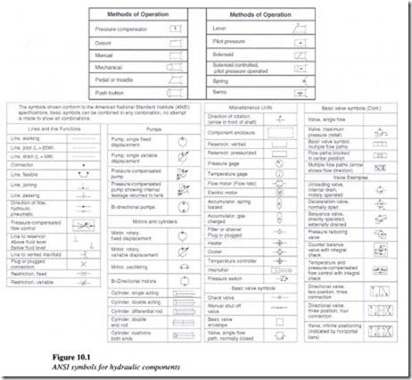
It is very important for a fluid power technician or a designer to have knowledge of each of the hydraulic components and their functions in a hydraulic circuit. Hydraulic circuits are developed by using graphical symbols for all of the components. Therefore it is pertinent to know the symbols of each and every component used in a hydraulic system.
The symbols discussed here conform to the American National Standard Institute (ANSI) standards and are tabulated below (see Figure 10.1).
