System capability
For a given material a particular problem with pneumatic conveying systems is the evaluation of their conveying potential; and even for a first approximation value. The capability of a pneumatic conveying system, in terms of achieving a given material mass flow rate, depends primarily on the following three parameters:
1. the diameter of the pipeline
2. the distance to be conveyed, and
3. the conveying line pressure drop available.
Air flow rate is a secondary function, being primarily dependent upon the pipeline bore and air pressure. It is, however, important with respect to achieving optimum con- veying conditions in a given pipeline. The properties of the material to be conveyed are also of paramount importance. Their main influence, however, in terms of material mass flow rate, is in placing an upper limit on the solids loading ratio at which the material can be conveyed under particular conditions, as shown in Figure 12.17.
Solids loading ratio – <1
The solids loading ratio of a conveyed material is the dimensionless ratio of the mass flow rate of the material being conveyed, m· p, to the mass flow rate of the air used for conveying, m·a:
The constant of 3.6 is required to render the parameter dimensionless since material flow rate is in tonne/h and air flow rate is in kg/s.
Since air is a compressible fluid its density changes with pressure and so the volu- metric flow rate of the conveying air can increase quite significantly along the length of a pipeline. Solids loading ratio, therefore, is a particularly useful parameter for describing the concentration of the material in the air in pneumatic conveying system pipelines, for it is a dimensionless quantity and its value remains essentially constant.
The influence of pipe bore
The mass flow rate of a material, m· p, can be expressed in terms of the solids loading ratio, ¢, at which the material is conveyed, by:
where · is the volumetric air flow rate, which is equal to C X A, in which C is the con- veying air velocity and A, the pipe section area, is equal to Trd2/4, where d is the pipe bore. Therefore,
For a given system, therefore, throughput capability can be increased quite considerably by increasing the pipe bore and so enable high material flow rates to be achieved. The air requirements, of course, also have to be increased in the same pro- portion in order to maintain an equivalent air velocity.
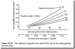
In terms of achieving a given material flow rate over a specified distance, pipeline bore is probably the main variable. Pressure drop is also important, but an increase in air supply pressure is not always possible. Pipeline bore also has a significant effect on the air only pressure drop value, and this is particularly important if a low pressure air supply is to be used. A significant portion of the available pressure could be taken up in getting the air through the pipeline.
The situation is illustrated in Figure 12.25, which is a repeat of Figure 10.5. This is a plot of the air only pressure drop for pipelines, drawn against air flow rate, with lines of constant pipe bore superimposed. It is drawn for pipelines 300 m in length. The influence of pipe bore on the air only pressure drop value is clearly shown. In most systems, discharge is to atmospheric pressure, and so conveying line exit air velocity is directly proportional to air flow rate. As a result, conveying line exit air velocities
have been included for reference, since air flow rate also has a significant effect on the air only pressure drop.
The influence of pressure drop
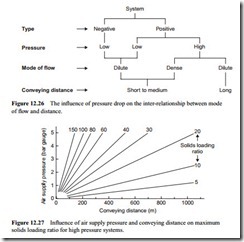
For a given system it is the pressure rating of the blower or compressor that is used to provide the air, which dictates how much and how far the material can be conveyed in a given bore of pipeline. The problem is summarized to a certain extent in the simplified diagram presented in Figure 12.26.
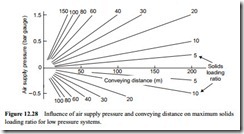
The inter-relating effects of conveying line pressure drop and conveying distance are further illustrated for high pressure systems in Figure 12.27, and for low pressure sys- tems in Figure 12.28. It must be stressed that these figures are only approximations for the purpose of illustration and should not be used for design purposes. Pipe bore, con- veying air velocity and material type all have an influence on the overall relationship.
Figure 12.27 shows that if very long conveying distances are required, the solids loading ratio will be relatively low, even with a high pressure system. With a low pressure
system the maximum solids loading ratio that can be achieved will be very low, and then only with a large bore pipeline.
For very short distances, however, it is quite possible to convey a material at high values of solids loading ratio, even with the limited pressure drop available with negative pressure systems, as will be seen in Figure 12.28, provided that the material is capable of being conveyed in this mode. Pressure gradient, therefore, is the parameter that will dictate the potential mode of conveying for a material that is capable of being conveyed in dense phase.


