Pipeline material
In nearly all the work presented so far only steel pipelines have been used and con- sidered. Other pipeline materials are sometimes used, and in particular rubber hose. Conveying data on alternative pipeline materials, however, is very limited. The use of rubber hose and some pressure drop data for the material was presented in Section 5.4.
Rubber hose
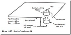
In many applications rubber hoses are used in pneumatic conveying lines. They find wide use in transport situations where a rigid line is not practicable. This is particu- larly the case in the loading and off-loading of ships. In order to determine the influence of rubber hose in pneumatic conveying, a number of programmes of tests were carried out with several fine materials conveyed over a distance of 40 m through a 53 mm bore pipeline [9, 10]. A sketch of the pipeline and high pressure blow tank test facility used is given in Figure 14.27.
In one programme barytes was conveyed and in another an oil well grade of cement was tested. They were first conveyed through pipeline no. 14, comprising 40 m of steel pipe and five 90° bends. For the second part of the programme 35 m of the steel pipeline was replaced by rubber hose, with the hose strapped to the steel pipeline to replicate the routing and the bend geometries over this length, in order to produce an identical pipeline. The location of the 35 m of rubber hose in the 40 m long pipeline is indicated in Figure 14.27.
The results for the barytes conveyed through the two pipelines are given in Figure 14.28. These are complete conveying characteristics for the material conveyed over as wide a range of conveying conditions as could be achieved. High pressure air was employed and as the pipeline was relatively short, solids loading ratios of up to 150 were obtained with the material.
With the two sets of data presented together, and with the same set of axes, direct visual comparison is possible. Despite the fact that the two pipelines are identical with respect to both conveying distance and the number and geometry of bends, significant differences between the two sets of conveying characteristics will be seen. Identical data for the oil well cement conveyed through these two pipelines is presented in Figure 14.29.
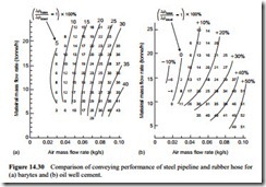
A comparison of the conveying performance for the two materials in the two pipelines, with respect to pipeline material, is given in Figure 14.30. The comparison is based on the ratio of the conveying line pressure drop for the hose divided by that for the steel pipeline, to achieve the same material flow rate. A rectangular grid was placed on each of the sets of conveying characteristics for the purpose.
Comparison with steel
From Figure 14.29 it can be seen that in very low velocity dense phase flow the resistance of the rubber hose is slightly lower than that of the steel pipeline. With high velocity, dilute phase conveying, however, the resistance of the rubber hose can be as much as 50 per cent greater than that of the steel pipeline. It is believed that the increase in pressure drop is due to the difference in coefficient of restitution between
steel and rubber. The rubber will absorb the energy of particles impacting and so the particles will rebound after impact at a much lower velocity. These particles will then have to be re-accelerated back to their terminal velocity, and it is this process that absorbs more energy with increase in velocity.
The results obtained with both the barytes and oil well and cement are very similar. The recommendation from this, therefore, is that, when and wherever possible, flexible rubber hoses should be used as close as possible to the start of a conveying line in order to reduce the overall pipeline resistance by ensuring that the hose is used at the low velocity end of the line.


