Typical pipeline and material influences
The scaling of the data, from the pipeline and the conditions from which the data was obtained, to the pipeline and conditions required, is a major feature of the design process when using test data. It was recommended in the logic diagrams that scaling should be carried out first with respect to conveying distance, and then with respect to pipeline bore. The determination of power requirements was also included in the logic diagrams.
In Chapter 8 several series of graphs were included to illustrate the relative influ- ences of the main parameters, and to show the potential of pneumatic conveying sys- tems for the transport of bulk particulate materials. Two different materials were considered, covering the extremes of material conveyability, and the influence on power requirements was introduced.
In Chapter 14 complete sets of conveying characteristics were presented for a num- ber of different materials, to illustrate the influence of material type. They were also used to show how conveying conditions could influence power requirements and specific energy, and they were used to show the potential influences of conveying distance on material flow rate. To illustrate these influences further and to provide some guidance on the effect of the different parameters at the various stages in the logic diagram, a further series of graphs are included. These also extend the analysis presented in Chapter 8 and so provide a little more detailed reasoning for the nature of the relationships.
The influence of conveying distance
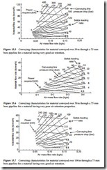
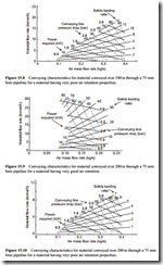
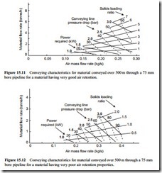
In Chapter 8 conveying distance was shown to have a very significant effect on both material flow rate and the solids loading ratio at which the material could be conveyed. The scaling of the sets of conveying characteristics in Chapter 14 also showed that there could be a significant change in air flow rate required for materials capable of dense phase conveying. In order to present a more complete picture and to show the influence of distance on material flow rate, solids loading ratio and air requirements, as well as conveying line pressure drop and power required complete sets of convey- ing characteristics are presented in Figures 15.5–15.12. The influence of material type is also included, with one set of data for dilute phase conveying and the other for mate- rials with dense phase capability.
Actual details of the scaling procedures necessary to obtain these different sets of conveying characteristics are given in Chapter 14.
For each material the conveying characteristics are included for conveying dis- tances of 50, 100, 200 and 500 m. They all relate to materials conveyed through a 75 mm bore pipeline.
These conveying characteristics provide the necessary design data on air mass flow rate, and also show the effect of air flow rate on material flow rate and power
requirements. In the case of both materials considered here an increase in air flow rate results in a decrease in material flow rate and an increase in power required.
This adverse effect of an increase in air flow rate is not the same for all materials, however. The relationships for materials such as PVC and PTA, shown in Figure 12.19, and nylon pellets shown in Figure 13.10, are very different, but this is only the case for the low velocity dense phase conveying of these materials. This is another reason why it is essential that reliable test data should be obtained for system design, particularly if it is a material for which no previous experience exists.
As these conveying characteristics provide design data on air flow rate it will be seen that the air requirements for a given conveying distance differ quite considerably for the two materials. For the material with very good air retention properties they also differ significantly with respect to conveying distance. The problem of matching air requirements in situations where different materials need to be conveyed with a com- mon system is considered in Chapter 19.


