Hydraulic circuits
In this section we shall take a look at how various types of hydraulic circuits are designed for efficient operation. We shall examine the following circuits:
• Control of a double acting hydraulic cylinder
• Regenerative circuit
• Pump unloading circuit
• Counterbalance valve application
• Hydraulic cylinder sequencing circuit
• Fail-safe circuits
• Speed control of a hydraulic motor
• Mechanical hydraulic servo system.
Control of a double acting hydraulic cylinder circuit
This circuit is designed as shown in Figure 10.2.
When the four-way valve is in its spring-centered position, the cylinder is hydraulically locked. Also the pump is loaded back to the tank at atmospheric pressure.
When the four-way valve is actuated into the flow path configuration of the left envelope, the cylinder is extended against its force load (F1oact) as oil flows from port P through port A. The oil at the rod end of the cylinder is free to flow back into the reservoir through the four-way valve from port B through port T. The cylinder will not extend if the oil in the rod end is not allowed to flow back to the reservoir.
When the four-way valve is de-activated, the spring-centered envelope prevails, and the cylinder is once again hydraulically locked.
When the four-way valve is actuated in the right envelope configuration, the cylinder retracts, as oil flows from port P through port B. Oil in the blank end is allowed to flow back to the reservoir from port A through port T of the four-way valve. At the end of the stroke, there is no system demand for oil. Therefore the pump flow goes through the relief valve at its set pressure, unless the four-way valve is de-activated. In any event, the system is protected from cylinder overloads.
The check valve prevents the load from retracting the cylinder, while it is being extended using the left envelope flow path configuration.
Regenerative circuit
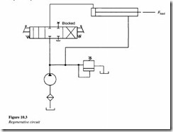
Figure 10.3 shows a regenerative circuit used to accelerate the extending speed of the double acting hydraulic cylinder.
In this system, both ends of the hydraulic cylinder are connected in parallel and one of the ports of the four-way valve is blocked. The operation of the cylinder during the retraction stroke is the same as that of a regular double acting cylinder.
Fluid flows through the DCV (direction control valve) via the right envelope during the retraction stroke. In this mode the fluid from the pump bypasses the DCV and enters the rod end of the cylinder. Fluid in the blank end drains back to the tank through the DCV as the cylinder retracts.
When the DCV is shifted to the left envelope configuration, the cylinder extends. The speed of extension is greater than that for a regular double acting cylinder. This is because the flow from the rod end (QR) regenerates with the pump flow (Qp) to provide a total flow rate (QT), which is greater than the pump flow rate to the blank end of the cylinder.
The equation for extending speed can be obtained as follows:
The total flow rate entering the blank end of the cylinder equals the pump flow rate plus
the regenerative flow rate coming from the rod end of the cylinder.
The regenerative flow rate equals the difference of the piston and rod areas (Ap- AR),
multiplied by the extending speed of the piston <VPex 1).
Solving for the extending speed of the piston, we have
The retracting speed of the piston equals the pump flow divided by the difference of the piston and rod areas.
It should also be borne in mind that the load-carrying capacity of a regenerative cylinder during its extension stroke is less than that obtained for a regular double acting cylinder.
Pump unloading circuit
Figure 10.4 depicts a circuit used for unloading a pump using an unloading valve.
In this circuit, the unloading valve opens as the cylinder reaches the end of its extension stroke. This is because the check valve keeps the high-pressure oil in the pilot line of the unloading valve. When the DCV is shifted to retract the cylinder, the motion of the cylinder reduces the pressure in the pilot line of the unloading valve. This resets the unloading valve until the cylinder is fully retracted at the point where the unloading valve unloads the pump. It is thus seen that the unloading valve unloads the pump at the end of the extending and retracting strokes as well as in the spring-centered position of the DCV.
Counterbalance valve application
Figure 10.5 illustrates the use of a counterbalance or backpressure valve to keep a vertically mounted cylinder in upward position during pump idling.
The counterbalance valve is set to open at a pressure slightly above the pressure required to hold the piston up. This permits the cylinder to be forced downward, when pressure is applied on the top. The open center direction control valve unloads the pump. The DCV used here is a solenoid-actuated, spring-centered valve with an open center flow path configuration.
10.4.5 Hydraulic cylinder sequencing circuit
From our earlier discussions, we have seen how a sequence valve can be used to create sequential operations in a hydraulic circuit.
The circuit depicted in Figure 10.6 contains a hydraulic system in which two sequence valves are used to control the sequence of operation of two double-acting cylinders.
When the DCV is shifted into its left envelope mode, the left cylinder extends completely and then the right cylinder extends. If the DCV is shifted into its right envelope mode, the right cylinder retracts fully followed by the left cylinder. This sequence of the cylinder operation is controlled by the sequence valves. The spring centered position of the DCV locks both the cylinders in place.
The best example of this circuit is the case of a production operation. The left cylinder should extend in order to accomplish the job of clamping a work piece with the help of a power vice jaw. The right cylinder extends to drive a spindle to drill a hole in the work piece. After the hole has been drilled, the right cylinder retracts first and then the left one. The sequence valve installed in the circuit ensures that these operations occur in a predefined fashion.
Fail-safe circuit
Fail-safe circuits are basically designed to prevent injury to the operator or damage to the equipment. In general they prevent any accidental fall or overloading of the equipment.
Figure 10.7 shows a fail-safe circuit in which the cylinder is prevented from falling in the event of a hydraulic line rupture.
To lower the cylinder, the pilot pressure from the blank end of the piston must pilot open the check valve at the rod end, in order to allow the oil to return to the reservoir through the DCV. This happens when the push button valve is actuated to permit pilot pressure actuation of the DCV or with direct manual operation of the DCV during pump operation. The pilot-operated DCV allows free flow in the opposite direction to retract the cylinder when this DCV returns to its spring offset mode.
Figure 10.8 is another example of a fail safe circuit in which overload protection is provided for the system components.
The direction control valve 1 is controlled by a push button three-way valve 2. When overload valve 3 is in its spring-offset mode, it drains the pilot line of valve 1. If the cylinder experiences excessive resistance during its extension stroke, the sequence valve 4 pilot-actuates overload valve 3. This drains the pilot line of valve 1, causing it to return to its spring-offset mode. If push button valve 2 is then operated, nothing will happen unless the overload valve 3 is manually shifted into its blocked port configuration. This ensures the protection of the system components against excessive pressure due to excessive cylinder load during the extension stroke.
Speed control of a hydraulic motor
Figure 10.9 shows a circuit in which speed control in a hydraulic circuit is accomplished using a pressure-compensated flow control valve.
The operation of the circuit is as follows:
• In the spring-centered position of the tandem four-way valve, the motor is hydraulically locked.
• When the four-way valve is actuated into the left envelope, the motor rotates in one direction. Its speed can be varied by adjusting the setting of the throttle of the flow control valve. The speed can be infinitely varied as the excess oil goes through the pressure relief valve.
• When the four-way valve is de-activated, the motor stops suddenly and gets locked.
• When the right envelope of the four-way valve is in operation, the motor rotates in the opposite direction. The pressure relief valve provides overload protection when the motor experiences an excessive torque load.
Mechanical hydraulic servo system
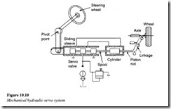
Figure 10.10 shows a mechanical hydraulic servo system with automotive power steering, the sequential operation of which occurs as follows:
• The input or command signal is the turning of the steering wheel.
• This results in movement of the valve sleeve, which ports oil to the actuator (steering cylinder).
• The piston rod moves the wheels through the steering linkage.
• The valve spool is attached to the linkage, thereby moving it.
When the valve spool has moved far enough, it cuts off the oil flow through the cylinder. This stops the motion of the actuator.
It is therefore clear that mechanical feedback re-centers the valve (servo valve) in order to stop motion at the desired point which in turn is determined by the position of the steering wheel. Additional motion of the steering wheel is required to cause further motion of the output wheels.
Incoming search terms:
- hydraulic circuit design
- content
- Hydraulic circuit design and analysis
- design of hydraulic circuits
- hydraulic circuit
- design of hydraulic circuit
- regenerative hydraulic circuit
- regenerative hydraulic circuit application
- design a hydraulic circuit using a 2 position dcv
- Hydraulic circuits
- cylinder lock circuit
- oil hydraulic circuit design
- hydraulic circuit pdf
- hydraulic circuit system of single acting cylinder
- hydraulic circuit to control a double acting cylinder
- hydraulic circuits in design of hydraulic and pneumatic systems
- hydraulic cirucit analysis
- hydraulic double pu
- hydraulic single acting cylinder circuit
- indahydraulic carcit
- setting up hyd circ
- single acting cylinder and air motor sequencing circuit
- actuator locking circuit in hydraulics
- Hydraulic circuit analysis
- application double pump hydraulic circuit
- design hydrolic circuit
- design of hydraulic circuit actuator in single acting
- designing a hydraulic circuit
- double acting cylinder in hydrau
- double acting hydraulic cylinder circuit
- double acting pneumatic cylinder circuit
- how is pump unloaded at the end of extension stroke of a hydraulic circuit
- How to analysis circuit in hydraulic
- How to design Hydr
- hydraulic actuator locking circuit
- hydraulic cir
- hydraulic circ
- hydraulic circiut
- hydraulic circu
- single acting hydraulic circuit


