Flovvrneters
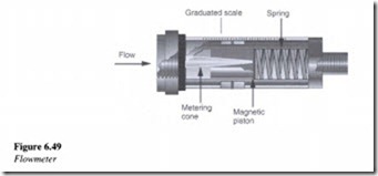
Flowmeters are used to measure flow in a hydraulic circuit. As shown in Figure 6.49, flowmeters mainly comprise of a metering cone and a magnetic piston along with a spring, for holding the magnetic piston in the no-flow position.
Flow meters are normally not bi-directional in nature. They in fact act as check valves and block flow in the reverse direction. Initially the fluid entering the device flows around the metering cone, exerting pressure on the magnetic piston and spring. With increase in flow in the system, the magnetic piston begins compressing the spring and thereby indicates the flow rate on a graduated scale.
Related posts:
Compressed Air Transmission and Treatment:AIR DRYERS
Air only relationships:Stepped pipelines and Air only pressure drop.
System selection considerations:Variables investigated
Moisture and condensation:Humidity and Specific humidity
Optimizing and up-rating of existing systems:The influence of changing pipeline diameter
Conveying capability:High pressure conveying – Part IV
Conveying characteristics:The determination of conveying characteristics
Control components in a hydraulic system:Hydraulic fuses.
The air relay and the force balance principle.
Modular valves and manifolds.
Sequencing Applications:Pneumatic limit switches
PROPERTIES OF PURE SUBSTANCES:PURE SUBSTANCE
ENERGY TRANSFER BY HEAT,WORK,AND MASS:ENERGY TRANSFER BY WORK
SUMMARY OF ENERGY TRANSFER BY HEAT,WORK,AND MASS
ENTROPY:MINIMIZING THE COMPRESSOR WORK
