Oil removal
The problem of oil removal is complicated by the fact that oil can exist in three forms: liquid, oil/water emulsions and oil vapour. Special filters are required to remove oil vapour and oil aerosol.
Modern oil removal filters are of the coalescing type and commonly use glass fibre elements. Oil particles impinge on and adhere to the fibres, resulting in a gradual build up of coalesced droplets. These droplets are driven to the outside of the material by the airstream, where the oil is stopped by a porous sock covering the element. It then flows by force of gravity to the bottom of the sock where it drops to the filter bowl. The oil is automatically drained from the filter. These filters are capable of removing the oil content in compressed air down to a level of 0.1 mg/m 3 or less.
Glass microfibres are considered to be an ideal filter medium for coalescing of liquid aerosols. This material is neither absorbent or adsorbent and consequently retains its original properties. It is superior to natural wool which has been used in the past. Glass microfibres are hydrophobic (water repellent) and so water tends to form on such fibres in droplet form rather than as a film, a condition which is favourable to filtration efficiency. Unfortunately, neither glass nor any other material is oleophobic (oil repellent) and oil will form as a film on glass microfibres, increasing their effective diameter. Allowance for this increase can be made and the oil film will not appreciably detract from the filtration efficiency, once the filter medium has been wetted. Glass microfibres in the range 0.5 to micron diameter yield the best results as filter coalescing media. The depth of the fibre bed and the ratio of the void space to fibre space are of critical importance in the proper operation of this type of filter. The application of coalescing filtration techniques to the removal of oil aerosols, although relatively new, is overcoming a long standing difficulty in the use of compressed air as a process and control medium. The coalescing filter has shown that it is a solution to the growing need for oil-fre0 air.
The mechanical sandwich construction of the two stage filter element, embedded between stainless steel support sleeves, assures high filtration efficiency even under changing pressures and flow directions. Due to the coalescing effect of the filter medium, the elements are self-regenerative in the removal of liquids (oil or water). It is advisable to fit pre-filters capable of removing dirt particles down to 5 micron or less, otherwise the
coalescing filter may become choked with dirt. High efficiency filters should be installed downstream of a dryer where used. Note that for some applications it may be necessary to combine coalescing filters with activated carbon filters to remove the residual oil vapour.
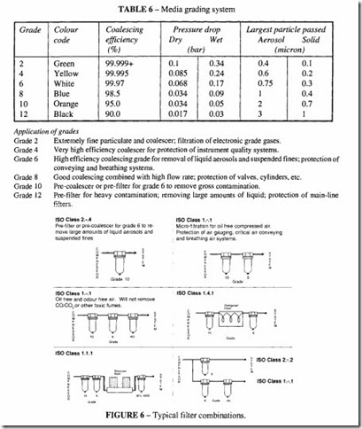
Table 6 gives some typical filter grades. Manufacturers have their own methods of designation, and it is wise to consult with them on specific applications. Figure 6 illustrates
some combinations. Two typical forms of construction are shown in Figures 7 and 8. Most filter bodies can incorporate a differential pressure gauge and an external automatic drain device.
Oil vapour
Oil-free air will still contain hydrocarbon vapours and odours which in the food, dairy, pharmaceutical and brewing industries must be removed. Activated carbon filters can be used for this purpose. These are incorporated downstream of the oil removal filters.

