Variable speed drives for other AC motors
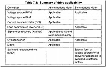
In general the voltage source PWM concept is also applicable to the majority of alternative motor designs. This principle is equally applicable in basic terms to the conventional and permanent magnet synchronous motor, and with some small adaptation to the switched reluctance motor. However, an exciter control is also required for a conventional synchronous motor.
A summary of possible alternative drive and motor combinations is shown in Table 7.1.
Variable speed drives for DC motors
A DC commutator motor requires a variable current to be applied to the armature, which is normally obtained by a controlled rectifier bridge, whereas the AC drive design illustrated in Figure 7.4 uses an uncontrolled rectifier. The DC motor drive also requires a field supply, which may be a constant voltage, or a controlled voltage in more complex control schemes.
Brushless DC motors use a modified PWM converter.
Drive controller algorithms
Manufacturers often use complex technical terminology to specify the type of control that their specific drive offers. The power electronics components in low voltage PWM drives do not differ very much from one manufacturer to another. An important consideration in the capability of a drive is its ability to deliver and control torque and speed, particularly at lower frequencies.
The control strategies are achieved by different algorithms programmed into the microprocessor of the drive, which ultimately determine the output torque of the motor. The algorithms require information about the motor in order to be effective. The characteristics of the motor such as volts, full load current and base speed are entered in the drive configuration during set up. Other parameters require the drive to perform a tuning routine on the motor to measure static and dynamic parameters. The drive monitors volts, amps and frequency continuously when running and may also measure speed and position of the rotor if an encoder is mounted on the motor shaft and fed back to the drive. The drive uses the motor information to model its response and to control the firing of the power transistors with the objective of obtaining optimum torque and control.
For centrifugal pumps it is unlikely that any special form of control is required as they are low starting torque loads. Special control forms may give secondary benefits from better motor control. With a positive displace ment pump much more care is required, as the power drawn is roughly proportional to the rotational speed, and in addition a high starting torque may be required especially for progressive cavity pumps (refer to Appendix A2.3 for further details).
Using the spare capacity of the drive microprocessor can allow control optimization to be built into a package.
Energy optimizing or “flux optimizing” techniques
Many VFDs incorporate an “energy optimizing” feature, which saves energy by reducing the motor magnetizing current at low mechanical loads. The principle is that at low load, with a centrifugal load, the motor does not need to produce such a strong magnetic field to produce torque. These efficiency improvements are relatively small; typically at 50% load and 90% speed, for a 22 kW (30 hp) motor, the inverter fed efficiency may be raised from 92% to 92.5%. This is usually much less than from the slowing down of the driven machinery, but still gives a tangible benefit.
Energy optimizing will also result in an improvement in the motor noise and vibration.
