Rotodynamic pumps
Pump principles and performance characteristics
A rotodynamic (centrifugal) pump is a dynamic device for increasing the pressure of a liquid. In passing through the pump, the liquid receives energy from the rotating impeller. The liquid is accelerated circumferential ly in the impeller, discharging into the casing at high velocity, which is converted into pressure as effectively as possible. The actual shapes of the hydraulic passages of the impeller and the casing are extremely important in order to attain the highest efficiency possible .
Since the pump is a dynamic device, it is convenient to consider the head generated rather than the pressure. The pump generates the same head of liquid whatever the density of the liquid being pumped.
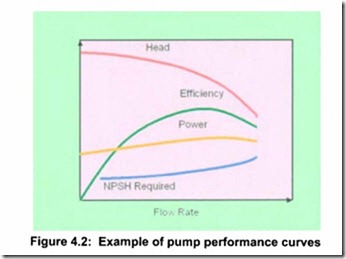
The standard convention for rotodynamic pumps is to draw the pump performance curves showing flow rate on the horizontal axis and head
generated on the vertical axis. Hydraulic efficiency, power & NPSH required (see Section 4.2.1.3 for explanation of NPSH), are also all con ventionally shown plotted against flow rate, as illustrated in Figure 4.2.
Effects of speed variation
As stated above , a rotodynamic pump is a dynamic device with the head generated by a rotating impeller. There is therefore a relationship between impeller peripheral velocity and generated head. Peripheral velocity is directly related to shaft rotational speed, for a fixed impeller diameter. Varying the rotational speed therefore has a direct effect on the performance of the pump. All the parameters shown in Figure 4.2 will change if the speed is varied and it is important to have an appreciation of how these parameters vary in order to safely control a pump at different speeds.
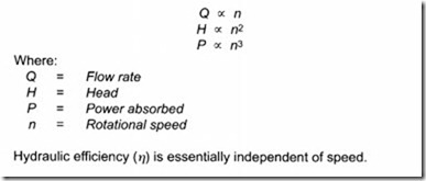
The equations relating the rotodynamic pump performance parameters of flow rate, head and power absorbed, to speed are known as the affinity laws:
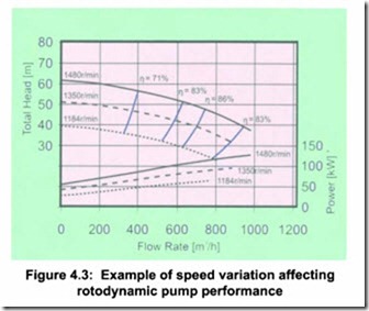
The implication of the squared and cubic relationships of head and power absorbed, is that relatively small changes in speed give very significant changes in these parameters as shown in an example of a rotodynamic pump in Figure 4.3.
Points of equal efficiency on the curves for the three different speeds are joined to make the iso-efficiency lines (blue), showing that efficiency remains constant over small changes of speed providing the pump continues to operate at the same position relative to its best efficiency point (BEP).
The affinity laws give a good approximation of how pump performance curves change with speed but in order to determine the actual perform ance of the pump in a system, the system curve also has to be taken into account, as will be explained later.
The power absorbed by magnetically driven pumps using metallic
containment shells includes both hydraulic power and the magnetic coupling power. Where the speed changes are large, or the speed is below 1000 r/min, advice from the pump manufacturer must be obtained. The hydraulic power obeys the affinity laws but the magnetic power absorbed follows a square law with speed. The two types of power must therefore be calculated separately for a change of speed.
This is explained further with a worked example in Appendix AS.
Effects of impeller diameter change
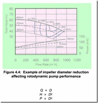
Changing the impeller diameter gives a proportional change in peripheral velocity, so it follows that there are equations, similar to the affinity laws, for the variation of performance with impeller diameter 0:
Efficiency varies when the diameter is changed within a particular casing. Note the difference in iso-efficiency lines in Figure 4.3 compared with Figure 4.4. The relationships shown here apply to the case for changing only the diameter of an impeller within a fixed casing geometry, which is a common practice for making small permanent adjustments to the performance of a centrifugal pump. Diameter changes are generally limited to a reduction of about 75% of the maximum, i.e. a head reduction to about 50%. Beyond this, the casing and impeller are mismatched and efficiency and NPSH are badly affected.
In contrast however, speed change can be used over a wider range without seriously reducing pump efficiency as long as the static head is not too high. Motor drive efficiency may however drop.
Certain high flow, low head pumps have performance curve shapes somewhat different from those illustrated, which are typical of radial flow types. Generally mixed flow and axial flow pumps have limited operating regions due to flow instabilities. This requires additional care in matching the pump to the system, when making changes to speed and impeller diameter.2 {The impeller diameter usually cannot be changed on axial flow pumps.)
Magnetically driven pumps, with metallic containment shells also need to be treated differently because a change of impeller diameter affects only the hydraulic power, not the magnetic drive power loss. Mechanical power loss in the drive is independent of diameter and so if the speed is unchanged, the magnetic losses will not change. See Appendix A5 for a worked example.
