Proportional-Flow Filters
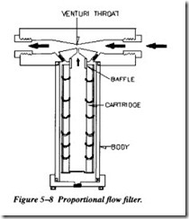
This type of filter operates on the venturi principle. As the fluid passes through the venturi throat, a drop in pressure is created at the narrowest point. Figure 5-8 illus trates a proportional-flow filter. A portion of the fluid flowing toward and away from the throat of the venturi flows through this passage into the body of the filter. A fluid passage connects the hollow core of the filter with the throat of the venturi. Thus, the low-pressure area at the throat of the venturi causes the pressurized fluid in the body of the filter to flow through the filter element, through the hollow core, and into the low-pressure area. The fluid is then returned to the system. Although only a portion of
the fluid is filtered during each cycle, constant recirculation through the system will eventually cause all the fluid to pass through the filter element.
Filter Rating
Filters are rated in several ways: absolute, mean, and nominal. The absolute filtration rating is the diameter, in microns, of the largest spherical particle that will pass through the filter under a certain test condition. This rating is an indication of the largest opening in the filter element. The mean filtration rating is the measurement of the average size of the openings in the filter element. The nominal filtration rating is usu ally interpreted to mean the size of the smallest particles of which 90 percent will be trapped in the filter at each pass through the filter element.
Filter Elements
Filter elements may be divided into two classes: surface and depth. Surface filters are made of closely woven fabric or treated paper with a uniform pore size. Fluid flows through the pores of the filter material and contaminants are stopped on the filter’s surface. This type of filter element is designed to prevent the passage of a high per centage of solids of a specific size.
Depth filters, on the other hand, are composed of layers of fabric or fibers, which pro vide many tortuous paths for the fluid to flow through. The pores or passages must be larger than the rated size of the filter if particles are to be retained in the depth of the medium rather than on the surface.
Filter elements may be of the 5-micron, woven-mesh, micronic, porous-metal, or magnetic type. The micronic and 5-micron elements have noncleanable filter media and are disposed of when they are removed. Porous-metal, woven-mesh, and mag netic filter elements are usually designed to be cleaned and reused.
Noncleanable 5-micron. The most common 5-micron filter medium is composed of organic and inorganic fibers integrally bonded by epoxy resin and faced with a metal lic mesh upstream and downstream for protection and added mechanical strength. Fil ters of this type are not to be cleaned under any circumstances.
Another 5-micron filter medium uses layers of very fine stainless-steel fibers drawn into a random but controlled matrix. Filter elements of this material may be either cleanable or disposable, depending on their construction.
Woven wire mesh. Filters of this type are made of stainless steel and are generally rated as 15 or 25 microns (absolute). This type of element is reusable.
Micronic hydraulic. The term micronic is derived from the word micron. It could be used to describe any filter element; however, through usage this term has become associated with a specific filter with a specially treated cellulose paper (Figure 5-9).
Magnetic filters. Some hydraulic systems have magnetic filters installed at strategic points. Filters of this type are designed primarily to trap any ferrous particles that may be in the system.
HEAT EXCHANGERS
The conversion of hydraulic force to mechanical work generates excessive heat. This heat must be removed from the hydraulic fluid to prevent degradation of the fluid and possible damage to system components.
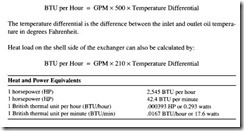
Heat goes into the hydraulic oil at every point in the system where there is a pressure loss due to oil How without mechanical work being produced. Examples are pressure relief and reducing valves, How control valves, and flow resistance in plumbing lines and through components. Hydraulic pumps and motors also produce heat at about 15 percent of their working horsepower. Power loss and heat generation due to these causes can be calculated with one of the following formulas:
The pressure (psi) for calculating heat generation in a flow control valve, for example, is the inlet minus the outlet pressure, or the pressure drop across the valve.
Sometimes power loss and heat generation occur intermittently, and to find the aver age amount of heat that will go into the oil, the average power loss should be calcu lated. Usually, taking an average over a 1-hour period should be sufficient. Therefore, hydraulic systems should include a positive means of heat removal. Normally, a heat exchanger is used for this purpose.
The exact size of a heat exchanger needed on a new system cannot be accurately calculated because of too many unknown factors. On existing systems, by making
tank measurements and measuring air and oil temperatures, a rather accurate calcu lation can be made of the heat exchanger capacity needed to reduce the maximum oil temperature.
The theoretical maximum cooling capacity of a heat exchanger for a hydraulic system will never have to be greater than the input horsepower to the system. Usually its capacity can be considerably less, based on the calculated input horsepower. A rule of-thumb is to provide a heat exchanger removal capacity of about 25 percent of the input horsepower. Rarely, even on inefficient systems, would a capacity of more than 50 percent be required.
In ordering a heat exchanger, the information furnished to the supplier must include the maximum rate of oil flow, in GPM, through the heat exchanger, and the horse power or BTU per hour of heat to be removed. On water-cooled models, state the maximum rate of water flow that will be available. For best water usage, the water flow should be approximately one-half of the oil flow. Specify the temperature of the cooling water.
Heat Load


