Proportional Valves
The solenoid valves described so far act, to some extent, like an electrical switch, i.e. they can be On or Off. In many applications it is required to remotely control speed, pressure or force via an electrical signal. This function is provided by proportional valves.
A typical two position solenoid is only required to move the spool between 0 and 100% stroke against the restoring force of a spring. To ensure predictable movement between the end positions the solenoid must also increase its force as the spool moves to ensure the solenoid force is larger than the increasing opposing spring force at all positions.
A proportional valve has a different design requirement. The spool position can be set anywhere between 0% and 100% stroke by varying the solenoid current. To give a predictable response the solenoid must produce a force which is dependent solely on the
current and not on the spool position, i.e. the force for a given current must be constant over the full stroke range. Furthermore, the force must be proportional to the current.
Figure 4.29 shows a typical response. The force from the sole noid is opposed by the force from a restoring spring, and the spool will move to a position where the two forces are equal. With a current of 0.75 A, for example, the spool will move to 75% of its stroke.
The spool movement in a proportional valve is small; a few mm stroke is typical. The valves are therefore very vulnerable to stiction, and this is reduced by using a ‘wet’ design which immerses the solenoid and its core in hydraulic fluid.
A proportional valve should produce a fluid flow which is pro portional to the spool displacement. The spools therefore use four triangular metering notches in the spool lands as shown on Figure 4.30. As the spool is moved to the right, port A will progressively link to the tank and port B to the pressure line.
The symbol for this valve is also shown. Proportional valves are drawn with parallel lines on the connection sides of the valve block on circuit diagrams.
Figure 4.30 gives equal flow rates to both A and B ports.
Cylinders have different areas on the full bore and annulus sides
(see Figure 5.4). To achieve equal speeds in both directions, the notches on the lands must have different areas. With a 2: 1 cylinder ratio, half the number of notches are used on one side.
Figure 4.31 shows the construction and symbol for a restricted centre position valve. Here the extended notches provide a restricted (typically 3%) flow to tank from the A and B ports when the valve is in the centre position.
So far we have assumed the spool position is determined by the balance between the force from the solenoid and the restoring force from a spring. Whilst this will work for simple applications, factors such as hydraulic pressure on the spool and spring ageing mean the repeatability is poor. Direct solenoid/spring balance is also not feasible with a pilot/main spool valve. What is really required is some method of position control of the spool.
To achieve this, the spool position must be measured. Most valves use a device called a Linear Variable Differential
Transformer (or LVDT) shown on Figure 4.32a. The LVD Tconsists of a soft iron core whose position is to be measured surrounded by three electrical windings. A high frequency (typically a few kHz) AC signal is applied to the centre winding which induces voltages into the other two windings. When the core is central, V 1 and V2 are equal but opposite in phase giving zero volts at V3.
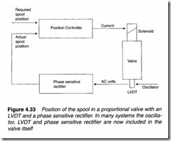
If the core moves away from the central position, to the left say, v2 will decrease, but vl will remain unchanged. v3 (which is the difference between V 1 and V2) thus increases and is in phase with the driving oscillator signal as shown on Figure 4.32b. If the core moves to the right V3 will also increase, but will now be anti-phase to the driving signal. The amplitude of V3 is proportional to the distance the core moves, and the phase depends on the direction. V3 is connected to a phase sensitive rectifier to give a bi-polar DC output signal V proportional to the core displacement.
A position control system can now be achieved as Figure 4.33. The demanded and actual spool positions can be compared by a position controller, and the solenoid current increased or decreased automatically until the position error is zero. In a pilot/main valve the position feedback will be taken from the main spool The spool position is determined by the solenoid current. A typical solenoid will operate over a range of about 0 to 1 amp. Power dissipation in the current controller is V x I watts where V is the volts drop and I the current. Maximum dissipation occurs at half current (0.5 A) which, with a typical 24 V supply, gives 12 watts. This implies substantial, bulky (and hence expensive), power transistors.
Current control is usually performed with Pulse Width Modulation (PWM) shown in Figure 4.34. Here the current is turned rapidly On and Off with the On/Off ratio determining the mean current. The control circuit is either turned fully on (low voltage drop, high current but low dissipation) or fully off (high voltage drop, zero current, again low dissipation). Because the dis sipation is low, smaller and cheaper transistors can be used.
Proportional valves operate with small forces from the solenoid and rely on small deflections of the spool. They are hence rather vulnerable to stiction which causes the valve to ignore small changes in demanded spool position. The effect is made worse if the valve spool is held in a fixed period for a period of time, allow ing the spool to settle. Dirt in the oil also encourages stiction as small dirt particles will increase the probability of the spool sticking.
A high frequency (typically a few kHz), signal is therefore added to the command signal as Figure 4.35. This is too fast for the valve to follow, but the small movement prevents the spool from staying in a fixed position. This action, called Dither, is normally factory set on the electronic control card described below.
It is not possible for a proportional valve to totally shut off flow in the centre, null, position unless the spool is manufactured with a small deadband as Figure 4.36. The result is a non-linear response
between demanded spool position and the resultant flow. In many cases this is of no concern, but if full reversing control is required the deadband may be a problem.
Most electronic control cards thus include a deadband compensation. This adds an adjustable offset to the reference signal in each direction effectively allowing the width of the deadband region to be controlled.
Sudden changes of speed imply large accelerations which in tum imply large forces since F = ma where F is the force, m is the mass
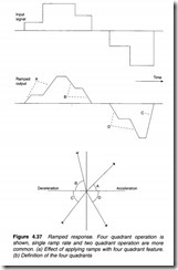
and a the acceleration. At best, sudden speed changes will result in noise from the system. More probably, however, the step forces will result in eventual damage and failure of piping, pumps and actuators. Most proportional valve control circuits therefore include methods by which the acceleration and deceleration can be con trolled as shown on Figure 4.37a and b. Here four ramp rates, two for acceleration and two for deceleration, soften the impact of the stepped demanded input signal. These ramp rates can be pre-set, usually by trim potentiometers on the electronic control card described below.
Figure 4.37 allows independent adjustment of acceleration and deceleration in all four quadrants (A,B,C and D). In simpler, (and hence cheaper), arrangements there may be two adjustable ramp rates for acceleration and deceleration (i.e. A and D are equal and B and C are equal), or two ramp rates according to slope sign (i.e. A and Care equal and Band Dare equal). In the simplest case there is only a single adjustable ramp rate (i.e. A, B, C and D are all equal).
A proportional valve must be used with some form of electronic control. Usually this is provided by a single card per valve. Cards can be mounted onto a back plate or, more usually, in a 19 inch rack. Figure 4.38 shows a typical card schematic.
Electronic cards for proportional valves usually run on a single 24 volt power supply, and require a current of around 1 to 2 amps; not insignificant when several cards are being used on the same project. The tolerance on the supply volts is usually quite wide, typically 20 to 30 V is quoted. Diode D 1 on the card protects against inadvertent supply reversal.
An on board power supply produces the multiple supply rails needed by the card circuit; + 15 V, + 10 V, -10 V and -15 V are common, with 5 Von microprocessor based cards. The +10 V and -10 V supplies are brought out to card terminal as supplies for a manually adjusted control potentiometer.
The Enable input allows current to pass to the valve solenoids. To enable the card, this must be connected to +24 V. This input can be used for safety critical functions such as emergency stops, over travel limits, safety gates etc.
The valve reference can come in many forms; the card illustrated uses three. First is a voltage signal with a range from + 10 V (solenoid A fully open) to -10 V (solenoid B fully open). This signal range is normally used with a manual control potentiometer.
The second signal accepts the standard instrumentation signal of 4-20 rnA to cover the same valve range. Current signals are less
prone to interference on long cable runs from the source to the card if a valve is being remotely controlled by a PLC or computer. The final reference comes from three fixed settings on potentiometers Pl to P3 mounted on the card itself. These are selected by digital signals which energize relays Rl to R3. The resulting reference is the sum of all three. In practice only one will be used, the others being zero. On some cards the source is selected by small switches on the card.
The resulting reference is then adjusted for gain, ramp rate (two quadrants shown on this example, single and four quadrants are also common) and deadband. The result is a required spool position which can be monitored with a voltmeter on TPl.
This setpoint is compared with the actual spool position, also available for monitoring on TP2, and the error used by a three term (proportional integral and derivative, PID) controller to adjust the current to solenoids A and B. Dither is added to the current signals to reduce stiction.
The spool position is monitored by an LVDT, fed from an oscil lator on the card. The signal from the LVDT is turned into a DC signal by a phase sensitive rectifier and fed back to the PID spool position controller.
Extensive monitoring and diagnostic facilities are built into the card. The desired and actual spool positions are a crucial test point as these show if the valve is responding to the reference signal. This provides a natural break point for diagnostics, as it shows if the reference is being received.
Another useful test points are LEDs Ia and lb. These glow with an intensity which is proportional to the solenoid current. If the valve sticks, for example, one LED will shine brightly as the PID controller sends full current to try to move the valve and reduce the error between TP 1 and TP2.
Other LED’s show the correct operation of the power supply, the state of the Enable signal, the selected fixed speed (if used) and a cable break fault from the LVDT.
Figure 4.38 is based on conventional electronic amplifiers. Increasingly microprocessors are being used, and although the operation is identical in function, it is performed by software. Serial communications, (RS232, RS485 or Fieldbus standards such as Profibus), is becoming common for adjusting the reference and reading the valve status. The settings of gains, ramp rates, fixed references etc. can be set remotely and easily changes by a computer or PLC control system.
With microprocessor based cards, stepper motors are often used to position the spool via a screw thread. This removes the need to balance a solenoid force against a spring force and combines the spool positioning actuator and feedback in the same device.
As electronics becomes smaller there is also a tendency to move the PID controller, current controllers and LVDT circuit into the valve head itself, i.e. everything to the right of TPl. Here the card simply provides a spool reference and a 24 V supply to the valve.
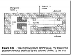
The valves described so far are directional valves, allowing flow to be controlled to and from a load. A proportional valve can also be used to control pressure. The principle is shown on Figure 4.39.
The solenoid spindle is aligned with a nozzle connected to the pressure line. For oil to pass from the pressure line back to tank, the force resulting from the fluid pressure must exceed the solenoid force. The relief valve will thus pass fluid back to the tank if the pressure force exceeds the solenoid force, and the pressure will be maintained at
The solenoid force is directly proportional to the solenoid current, so the pressure is also directly proportional to the current. The range of the relief valve is set by the nozzle area, and manufacturers supply nozzle inserts with different areas.
The circuit of Figure 4.39 can only handle a small fluid flow, so a practical valve will incorporate a proportional valve pilot stage linked to a main stage in a similar manner to the manually set spring operated relief valve of Figure 2.6b.


