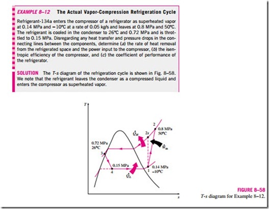
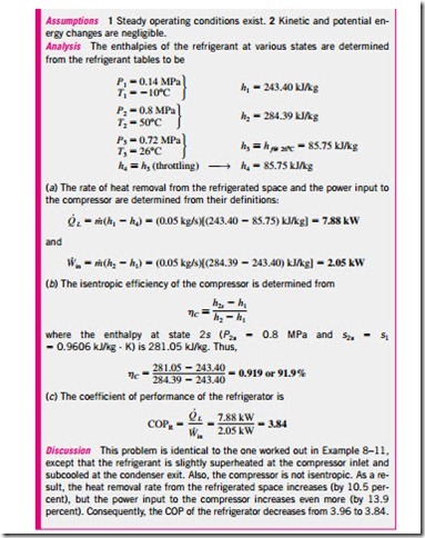
■ ACTUAL VAPOR-COMPRESSION REFRIGERATION CYCLE
An actual vapor-compression refrigeration cycle differs from the ideal one in several ways, owing mostly to the irreversibilities that occur in various components. Two common sources of irreversibilities are fluid friction (causes pressure drops) and heat transfer to or from the surroundings. The T–s diagram of an actual vapor-compression refrigeration cycle is shown in Fig. 8–57.
In the ideal cycle, the refrigerant leaves the evaporator and enters the compressor as saturated vapor. In practice, however, it may not be possible to control the state of the refrigerant so precisely. Instead, it is easier to design the system so that the refrigerant is slightly superheated at the compressor inlet. This slight overdesign ensures that the refrigerant is completely vaporized when it enters the compressor. Also, the line connecting the evaporator to the compressor is usually very long; thus the pressure drop caused by fluid fric- tion and heat transfer from the surroundings to the refrigerant can be very significant. The result of superheating, heat gain in the connecting line, and pressure drops in the evaporator and the connecting line is an increase in the specific volume, thus an increase in the power input requirements to the compressor since steady-flow work is proportional to the specific volume.
![]() The compression process in the ideal cycle is internally reversible and adiabatic, and thus isentropic. The actual compression process, however, will involve frictional effects, which increase the entropy, and heat transfer, which may increase or decrease the entropy, depending on the direction. Therefore, the entropy of the refrigerant may increase (process 1-2) or de- crease (process 1-2′) during an actual compression process, depending on which effects dominate. The compression process 1-2′ may be even more desirable than the isentropic compression process since the specific volume of the refrigerant and thus the work input requirement are smaller in this case. Therefore, the refrigerant should be cooled during the compression process whenever it is practical and economical to do so.
The compression process in the ideal cycle is internally reversible and adiabatic, and thus isentropic. The actual compression process, however, will involve frictional effects, which increase the entropy, and heat transfer, which may increase or decrease the entropy, depending on the direction. Therefore, the entropy of the refrigerant may increase (process 1-2) or de- crease (process 1-2′) during an actual compression process, depending on which effects dominate. The compression process 1-2′ may be even more desirable than the isentropic compression process since the specific volume of the refrigerant and thus the work input requirement are smaller in this case. Therefore, the refrigerant should be cooled during the compression process whenever it is practical and economical to do so.
In the ideal case, the refrigerant is assumed to leave the condenser as saturated liquid at the compressor exit pressure. In actual situations, however, it is unavoidable to have some pressure drop in the condenser as well as in the lines connecting the condenser to the compressor and to the throttling valve. Also, it is not easy to execute the condensation process with such precision that the refrigerant is a saturated liquid at the end, and it is undesirable to route the refrigerant to the throttling valve before the refrigerant is completely condensed. Therefore, the refrigerant is subcooled somewhat before it enters the throttling valve. We do not mind this at all, however, since the refrigerant in this case enters the evaporator with a lower enthalpy and thus can absorb more heat from the refrigerated space. The throttling valve and the evaporator are usually located very close to each other, so the pressure drop in the connecting line is small.

