Feeding requirements
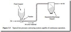
For a given conveying system the air mover can be positioned at either end, as will be seen with Figure 3.3. If the air is blown into the pipeline, therefore, the air at the feed point will be at a pressure close to that of the air supply. In this case the material has to be fed into the pipeline at pressure, and so consideration has to be given to the possibility of air leakage across the device. If the air mover is positioned downstream of the system, so that it acts as an exhauster to the separator/discharge hopper, the air at the material feed point will be close to atmospheric pressure. In this case the effect of a pressure gradient on the feeding device need not be taken into account.
A further requirement of the feeding device is that it should feed the material into the conveying line at as uniform a rate as possible. This is particularly so in the case of dilute phase systems, for the material is conveyed in suspension and quite high values of minimum conveying air velocity have to be maintained. With a mean conveying air velocity over the length of the pipeline of 20 m/s, for example, it will only take about 5 s for the air to pass through a 100 m long pipeline.
If there are any surges in material feed, the pipeline could be blocked very quickly. Alternatively, if the air mover has a pressure rating to make allowance for such surges, the output from the system could be increased if the flow rate, and hence the conveying line pressure drop, was kept constant at a higher value to match the rating more closely.
Flow metering
Positive displacement feeding devices, such as screws and rotary valves, can serve the dual purpose of metering the material into the pipeline, while effecting the airlock that is necessary for successful operation, in the case of positive pressure systems. Some feeders act only as airlocks and so require additional equipment to meter the material
into the conveying line. Some feeders have no moving parts, and so particular attention is given to them, as their means of material flow control may not be obvious.
