Continuous rotation hydraulic motors
Continuous rotation hydraulic motors are actuators, which can rotate continuously. Instead of acting on (or pushing) the fluid as pumps do, motors are acted upon by fluids. In this way, hydraulic motors develop torque and produce continuous rotary motion. Since the casing of a hydraulic motor is pressurized from an outside source, most hydraulic motors have casing drains to protect their shaft seals.
These are further classified as:
• Gear motors
• Vane motors and
• Piston motors.
Let us discuss each of the motor types individually.
Gear motors
Gear motors are simple in construction. A gear motor develops torque due to the hydraulic pressure acting on the surfaces of the gear teeth. A cross-section of a typical gear motor is illustrated in Figure 4.3.
By changing the direction of the flow of fluid through the motor, the direction of rotation of the motor can be reversed. As in the case of a gear pump, the volumetric displacement of the motor is fixed. The gear motor is not balanced with respect to pressure loads. The high pressure at the inlet, coupled with the low pressure at the outlet, produces a large side load on the shaft and bearings, thereby limiting the bearing life of the motor.
Gear motors are normally limited to operating pressures of around 140 kg/cm2 (roughly 2000 psi) and operating speeds of 2400 rpm. They are available with a maximum flow capacity of 550 lpm (liters per minute).
Hydraulic motors can also be of the internal gear type. The internal gear type motors can operate at higher speeds and pressures. They also have greater displacements than the external motors. Screw-type motors also form part of gear motors. As in the case of pumps, screw-type hydraulic motors use three meshing screws. The rolling screw set results in an extremely quiet operation. Screw type motors can operate at pressures up to 210 kg/cm2 (2990 psi approximately) and can have displacement volumes up to 0.227 liter.
The main advantages associated with gear motors are its simple design and cost effectiveness. They also possess good tolerance to dirt. The main disadvantages with gear motors are their lower efficiency levels and comparatively higher leakages.
Vane motors
The internal construction of the vane motors is similar to that of a vane pump; however the principle of operation differs.
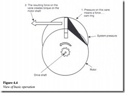
Vane motors develop torque by virtue of the hydraulic pressure acting on the exposed surfaces of the vanes, which slide in and out of the rotor connected to the drive shaft.
As the rotor revolves, the vanes follow the surface of the cam ring because springs are used to force the vanes radially outward. Figure 4.4 illustrates the basic operation of a vane motor.
No centrifugal force exists until the rotor starts to revolve. Therefore, the vanes must have some means other than the centrifugal force to hold them against the cam ring. Some designs use springs, while other types use pressure-loaded vanes. The sliding action of the vanes forms sealed chambers, which carry fluid from the inlet to the outlet.
Balanced and unbalanced-type vane motors
Figure 4.5(a) shows an unbalanced-type vane motor comprising of a circular chamber having an eccentric rotor and carrying several spring or pressure-loaded vanes. A higher force is exerted by the fluid on the upper vanes since fluid flowing through the inlet port finds more area of the vanes exposed in the upper half of the motor. This results in the counter-clockwise rotation of the rotor. The motor displacement here is a function of its eccentricity.
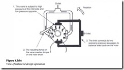
In the unbalanced type, as all the inlet pressure acts on one side of the rotor, the radial load on the shaft bearing is quite large. This problem is alleviated to a large extent by using a balanced vane motor, a schematic of which is illustrated in Figure 4.5(b).
In the balanced type, a double-lobed ring with diametrically opposed ports is provided. Here the side force that is exerted on one side of the bearing is canceled by an equal but opposite force from the pressure port located diametrically opposite. The like ports are usually connected internally so that only one inlet and outlet ports are brought outside.
Vane motors are universally of the balanced design type. Since vane motors are hydraulically balanced, they are fixed displacement units. These motors can operate at pressures of up to 175 kg/cm2 (2490 psi) and speeds up to 4000 rpm. The maximum flow usually delivered by these motors is in the range of 950 lpm. The vane-type motors have more internal leakage as compared with the piston type and are therefore not recommended for use in servo control systems.


