Hydraulic pumps
Objectives
After reading this chapter, the student will be able to:
• Distinguish between positive and non-positive displacement pumps
• Understand the principle of operation of gear, vane and piston pumps
• Differentiate between fixed and variable displacement pumps, external and internal gear pumps as well as axial and radial piston pumps
• Explain how pressure-compensated pumps work
• Identify the various types of pumps used in hydraulics
• Select and size pumps for various hydraulic applications
• Carry out basic maintenance activities on the pumps.
Principle of operation
The sole purpose of a pump in a hydraulic system is to provide flow. A pump, which is the heart of a hydraulic system, converts mechanical energy, which is primarily rotational power from an electric motor or engine, into hydraulic energy. While mechanical rotational power is the product of torque and speed, hydraulic power is pressure times flow. The pump can be designed in such a way that either flow or pressure is fixed, while the other parameter is allowed to swing with the load. In other words, by fixing the pump flow, the pressure goes up as the load restriction is increased. Conversely, the flow goes down with an increase in load restriction when the pump delivers fixed pressure.
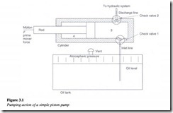
The pumping action is the same for every pump. Due to mechanical action, the pump creates a partial vacuum at the inlet. This causes the atmospheric pressure to force the fluid into the inlet of the pump. The pump then pushes the fluid into the hydraulic system (Figure 3.1).
The pump contains two check valves. Check valve 1 is connected to the pump inlet and allows fluid to enter the pump only through it. Check valve 2 is connected to the pump discharge and allows fluid to exit only through it.
When the piston is pulled to the left, a partial vacuum is created in the pump cavity 3.
This vacuum holds the check valve 2 against its seat and allows atmospheric pressure to push the fluid inside the cylinder through the check valve 1. When the piston is pushed to the right, the fluid movement closes check valve 1 and opens outlet valve 2. The quantity
of fluid displaced by the piston is forcibly ejected from the cylinder. The volume of the fluid displaced by the piston during the discharge stroke is called the displacement volume of the pump.
