combination pumps
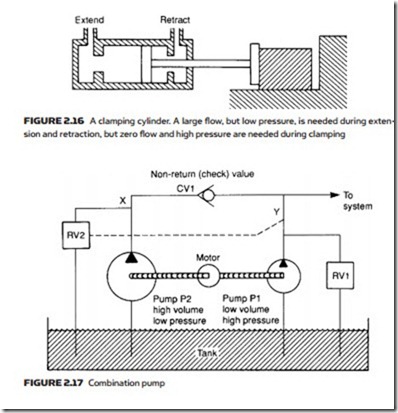
Many hydraulic applications are similar to Figure 2.16, where a workpiece is held in place by a hydraulic ram. There are essentially two distinct requirements for this operation. As the cylinder extends or retracts a large volume of fluid is re- quired at a low pressure (sufficient just to overcome friction). As the workpiece is gripped, the requirement changes to a high pressure but minimal fluid volume.
This type of operation is usually performed with two separate pumps driven by a common electric motor as shown in Figure 2.17. Pump P1 is a high-pressure low- volume pump, while pump P2 is a high-volume low-pressure pump. Associated
with these are two relief valves RV1 and RV2 and a one-way check (or non-return) valve which allows flow from left to right, but blocks flow in the reverse direction.
A normal (high-pressure) relief valve is used at position RV1 but relief valve RV2 is operated not by the pressure at point X, but remotely by the pressure at point Y. This could be achieved with the balanced piston valve of Figure 2.6 or,
more commonly, the sequence valve of Figure 4.27. In low-pressure mode both relief valves are closed and both pumps P1 and P2 deliver fluid to the load, the majority coming from pump P2 because of its higher displacement.
When the workpiece is gripped, the pressure at Y rises, and relief valve RV2 opens, causing all the fluid from pump P2 to return straight to the tank and the pressure at X to fall to a low value. Check valve CV1 stops fluid from pump P1 passing back to the tank via relief valve RV2; consequently pressure at Y rises to the level set by relief valve RV1.
This arrangement saves energy as the large volume of fluid from pump P2 is returned to the tank at a very low pressure, and only a small volume of fluid from pump P1 is returned at a high pressure. Pump assemblies similar to that shown in Figure 2.17 are called combination pumps and are manufactured as complete units with motor, pumps, relief and check valves prefitted.
