Hydraulic motors
Objectives
After reading this chapter, the student will be able to:
• Differentiate between hydraulic pumps and motors
• Understand and describe the design and construction of various motors used in hydraulics
• Explain the operation of the various hydraulic motors of the likes of gear, vane and piston motors and also evaluate their performance by determining their mechanical, volumetric and overall efficiencies
• Select and size motors for hydraulic applications
• Understand the performance parameters of hydraulics motors.
Basic principles
Hydraulic motors are classified as rotary actuators. But strictly speaking, the term ‘Rotary actuator’ is reserved for a particular type of unit whose rotation is limited to less than 360°. Hydraulic motors are used to transmit fluid power through linear or rotary motion. They resemble pumps very closely in construction. However, as already understood, pumps perform the function of adding energy to a hydraulic system for transmission to some remote point, while motors do precisely the opposite. They extract energy from a fluid and convert it to a mechanical output to perform useful work. To put it more simply, instead of pushing on the fluid as the pump does, the fluid pushes on the internal surface area of the motor, developing torque. Since both the inlet and outlet ports in a motor may be pressurized, most hydraulic motors are externally drained.
Hydraulic motors can be of limited rotation or continuous rotation type. Limited rotation motors are called oscillation fluid motors as they produce a reciprocating motion. Continuous rotation motors (hydraulic motors) as mentioned earlier are in reality pumps, which have been redesigned to withstand the different forces that are involved in motor applications.
Hydrostatic transmissions are hydraulic systems specifically designed to have a pump drive a hydraulic motor. Thus, a hydraulic transmission system simply transforms mechanical power into fluid power and then reconverts the fluid power into shaft power.
In this chapter, we shall examine the various types of hydraulic motors from the design
and construction point of view and also evaluate their performance. Hydraulic motors can be classified into two types:
1. Limited rotation hydraulic motors
2. Continuous rotation hydraulic motors.
Let us now examine each of these types in detail.
Limited rotation hydraulic motor
A limited rotation hydraulic motor provides a rotary output motion over a finite angle. This device produces a high instantaneous torque in either direction and requires only a small amount of space and simple mountings.
Rotary motors consist of a chamber or chambers containing the working fluid and a movable surface against which the fluid acts. The movable surface is connected to an output shaft to produce the output motion.
Figure 4.1 shows a direct acting vane-type actuator. In this type, fluid under pressure is directed to one side of the moving vane, causing it to rotate. This type of motor provides about 280° rotation.
Rotary actuators are available with working pressures up to 350 kg/cm2 (4978 psi). They are typically foot mounted, flanged or end mounted. Most designs provide cushioning devices. In a double vane design similar to the one depicted in the figure above, the maximum angle of rotation is reduced to about 100°. However in this case, the torque-carrying capacity is twice that obtained by a single vane design.
Torque capacity analysis of limited rotation hydraulic actuators with single rotating vane
Nomenclature
Let
RR be the outer radius of the rotor in meters
Rv be the outer radius of the vane in meters
L be the width of the vane in meters
P be the hydraulic pressure in psi or Pascal
F be the hydraulic force acting on the vane in Newton
A be the surface area of the vane in contact with oil in meter2 and
T be the torque capacity in Newton meter.
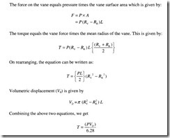
The force on the vane equals pressure times the vane surface area which is given by:
It is observed from the above equation that torque capacity can be increased either by increasing the pressure or by increasing the volumetric displacement or both.
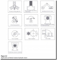
The various applications of rotary type limited rotation motors are (Figure 4.2):
• Conveyor sorting
• Valve turning
• Air bending operation
• Flip over between workstations
• Positioning for welding
• Lifting, rotating and dumping.


