Fluid conductors – hydraulic pipes and hoses
Introduction
Efficient transmission of power from one location to the other is a key element in the design and performance of a hydraulic system. This is known as fluid conducting. Fluid conductors comprise that part of the hydraulic system that is used to carry fluid to the various components. These conductors include the likes of steel tubing, steel pipes and hydraulic hoses.
In an actual hydraulic system, the fluid flows through a distribution network consisting of pipes and fittings, which carry the fluid from the reservoir through the operating components and back to the reservoir. Since power is transmitted throughout the system by means of this network, it is highly imperative that this network be properly designed to ensure efficient operation.
Steel piping
Steel pipes are often preferred over other conductors from the standard point of performance and cost. However since welding is required to be carried out on these pipings to ensure maximum leak protection, they are quite difficult to assemble. Another factor to be reckoned with is that they require costly flushing during start-up, to ensure a contaminant free environment. Although steel pipes are specified by their nominal outside diameter, their actual flow capacity is determined by their inside area.
One can classify a piping system into two types:
1. Metallic piping
2. Non-metallic piping.
The choice regarding the type of piping to be used for a system, primarily depends on its operating pressures and flow rates. Additionally, it also depends on environmental conditions such as the type of fluid, operating temperatures and atmospheric conditions.
Let us study the various types of pipes and their fittings used in a hydraulic system.
Metal piping
A pipe is a device used to convey fluids from one point to another without any physical movement on its part. Metallic pipes are the ones made from iron or steel. In order to have a common platform for specifying pipes all over the world, pipe sizes are standardized and are usually expressed in inches or millimeters. As a rule the size of a pipe is given in terms of its outside diameter or inside diameter.
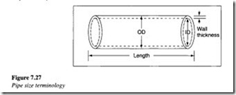
Figure 7.27 shows the cut section of a pipe and the terminology associated with it.
The principal dimensions with regard to pipes are:
• Outside diameter
• Inside diameter
• Wall thickness and
• Length.
Commercial pipelines up to 12 in. (305 mm) in size are designated by their inside diameters while pipe sizes above 12 in. (305 mm) are designated by their outside diameters.
Different metals have different characteristics, which render them usable for a variety of applications. An alloy is a metal made up of two or more metals, which dissolve into each other when melted together. Mixing a metal with a non-metal can also form an alloy. Metals are generally referred to as ferrous or non-ferrous metals. A ferrous metal is one that contains iron, while a non-ferrous metal does not contain iron. Piping is commonly made of wrought iron, cast iron or steel. The difference between the three is largely the carbon content in each of them. In addition to the common ferrous and non-ferrous metals used in piping material, there are some exclusive metals that are used in special piping applications. Aluminum pipes are light in weight and corrosion resistant, although they experience a decrease in strength with increase in temperature. Lead pipes are also considered suitable for highly corrosive fluids. Piping made from special materials is more expensive. Stainless steel, a common type of ferrous metal, is an alloy of steel and chromium.
Pipe schedules and codes
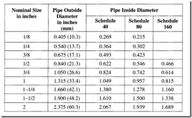
In the past, all piping was designated as standard, extra strong and double extra strong. That system allowed no variation for the wall thickness. Also, as the piping requirements started increasing, a greater variation was needed for specifying the pipes. As a result, piping today is classified according to a schedule. The most common schedule numbers in practice are 40, 80, 120 and 160. For pipe diameters ranging from 118 in. (15 mm) to 10 in. (250 mm), the dimensions of standard steel pipe correspond to schedule 40.
The standard steel pipes correspond to schedule 40 pipes with a wall thickness of 6 mm. The dimensions of extra strong steel pipes are the same as schedule 80 pipes ranging from diameters 15 to 200 mm.
For schedule numbers ranging from 10 to 160, the basic difference is the wall thickness. When the wall thickness of any given pipe size is increased, the inside diameter of the pipe decreases.
Due to the increasing variety and complexity of requirements for piping, a number of engineering societies and standards have devised codes, standards and specifications that cater to a vast majority of applications.
Some codes provide the formulae for determining the minimum pipe size and the minimum wall thickness for use in a given application. Some codes provide information on
the pipe material, method of manufacture (seamless or welded), ASTM (American Society of Testing and Materials) specification number, the grade of pipe and the stress that can be exerted on the pipe at various conditions of pressure and temperature. By consulting these codes, a designer can determine exactly the type of specification for a particular application. Selecting a pipe according to code recommendations is similar to the procedure adopted by an automobile mechanic who refers the operation and maintenance manual to determine the type of oil filter that is to be fitted for a particular car.
The pipe schedules commonly used in hydraulic systems are 40, 80 and 160. The classification has been done based on their nominal size and schedule numbers.
The ANSI (American National Standards Institute) has established a code for the identification of pipelines. This code involves the use of legends, nameplates or tags and colors. The code states that, ‘Identification of the contents of a piping system shall be by a lettered legend giving the name of the contents in full or in abbreviated form’. All the pipes are color coded with respect to their content, for easy identification. As shown in the table below, the use of colors provides a general indication of the type of material carried by the pipe.
Pipe fittings
The components used in a piping system to connect the various sections of the pipe in order to change the direction of flow, are called fittings. Fittings are made from a number of materials including steel, bronze, cast iron, plastic and glass.
Standards have been established to ensure that fittings are made from proper materials
and are able to handle the designed pressures. Some of the important functions of these fittings are:
• Changing the direction of flow
• Providing branch connections
• Changing the size of lines
• Closing lines
• Connecting lines.
Fittings for changing the direction of flow
To change the direction of flow, the fittings that are normally used are referred to as elbows. Elbows generally come in all angles but those that are commonly used are the 45° and 90° ones.
Figure 7.28 shows two common types of elbows used in industrial hydraulic applications.
A large radius fitting has the more gradual curve of the two. Along with the diameter and schedule of the pipe, elbows are also specified with center-to-face dimensions. It is the distance between the center of the fitting (A) and a line (C) drawn down from the face (D) of the fitting at the other end. In the elbow of larger radius, the center-to-face distance is always 1.5 times the diameter of the fitting. This type of elbow is used in applications where the rate of flow is critical and there is limitation regarding space. In a short radius elbow, the center-to-face distance is equal to the pipe diameter.
Fittings for changing the size of the pipelines
The function of the reducer is to reduce the line to a smaller pipe size. One reason for doing so is to increase the pressure in the system.
As in the case of elbows, we can see from Figure 7.29 that there are different types of fittings that can be used in a piping system, in order to meet the above requirements.
Pipe joints
Pipe joints can be of the screwed, flanged or welded type. Each of these joints which are widely used, have their own advantages and disadvantages.
Screwed fittings are joined to the pipe by means of threads. The main advantage of the threaded joints is that the pipe length can be easily tailored at a later stage. As a threaded joint has metal-to-metal contact between the threads of two mating parts of the pipe, the risk of leakage is high. Hence sealing of the threaded joint becomes very important. The traditional method of providing a seal between the mating threads is to coat the threads with a paste dope. In recent years, the invention of Teflon sealing tapes has made for a more effective solution. The Teflon (being a registered trademark of Du Pont De Neumors and Company) tape can be simply wound over the threads for sealing.
Flanged fittings are either forged or made as cast pipe fittings. A flange is a rim or ring at the end of the fitting, which mates with another section of the pipe. Pipe sections can also be made with flanged ends. Flanges are joined either by being bolted together or by being welded together. The flanged faces again have metal-to-metal contact and proper sealing needs to be provided between the two mating surfaces to avoid leakages. A gasket is usually inserted between the mating surfaces of two flanges, which are bolted together. Normally, compressed asbestos gaskets can be used under conditions of normal pressure and temperature. However, when the system operates under higher pressure and temperature conditions, higher-grade gaskets are used.
Other pipe fittings used in flanged connections include expansion joints and vibration dampeners. Expansion joints have three functions:
1. They compensate for slight changes in the length of the pipes, by allowing the joined sections of rigid pipes to expand or contract with changes in temperature.
2. They allow pipe motion either to the side or along the length of the pipe, as the pipe shifts after installation.
3. They help dampen vibration to some extent and reduce the noise carried along the pipe and originating from distant pumps.
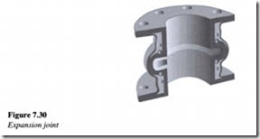
A typical expansion joint is shown in Figure 7.30.
It has a leak proof tube that extends through the bore and forms the outside surface of the flanges. Natural or synthetic rubber compounds are used for this purpose, depending on the type of application. Other types of expansion joints include metal bellows (corrugated type), spiral wound types and slip joint types.
Vibration dampeners are designed specifically to absorb vibration because vibrations reduce the life of the pipes as well as the operating equipments. They also eliminate line noises carried by the pipes.
A typical vibration damper is shown in Figure 7.31.


