Single blow tank systems
A particular problem with single blow tank system is that conveying is not continuous, as it can be with rotary valve and screw feeding systems. In order to achieve an equivalent material mass flow rate, therefore, instantaneous values of the flow rate during conveying have to be somewhat higher. This point was illustrated earlier with Figure 2.7 in Chapter 2.
Blow tanks without a discharge valve
The simplest form of blow tank is one that has no discharge valve. Such an arrange- ment is shown in Figure 4.8. This is shown in a top discharge configuration with a flu- idizing membrane, but any other type of top discharge blow tank could equally have been shown. Although there is no valve in the material discharge line, other valving is necessary. These valves, however, are not subject to the severe duty of a valve in the conveying line. With bottom discharge blow tanks a discharge valve is generally required simply to keep the material in the blow tank, for some materials will flood feed into the pipeline and block it.
A valve is required to isolate the blow tank from the material supply hopper, so that the blow tank can be pressurized, and a vent line valve is needed to allow the blow tank to be vented while it is being filled from the hopper above. If a vent on the blow tank is not used it will take considerably longer to fill the blow tank, for the air in the blow tank has to be displaced, and if it is not vented it will interfere with the flow of material from the hopper as this will be the only path of exit for the air. These valves are either fully open or closed. Valves, or possibly flow restrictions or orifices, are required in the
air supply lines in order to provide the necessary degree of control over the material discharge rate from the blow tank.
Conveying cycle analysis
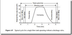
With the arrangement shown in Figure 4.8 the blow tank starts to pressurize as soon as the vent line valve is closed. Both the blow tank and conveying line have to be pressurized to a certain extent before any material is delivered from the pipeline, and this process can take a significant proportion of the total cycle time. Even when the material is first discharged from the conveying line, the pressure, and hence conveying rate, will have to reach steady state values. The pressure builds up gradually as more material is con- veyed, but it is a relatively slow process.
Towards the end of the conveying cycle, when the blow tank has almost been dis- charged, the blow tank has to be de-pressurized and the entire conveying line has to be cleared of material and vented. This process also takes a significant amount of time, particularly if the pipeline is long. The time required to fill the blow tank and set the valves has to be taken into account in addition. This type of blow tank system, how- ever, is very easy to operate and maintenance costs are very low.
For material testing and research purposes this type of blow tank is very convenient since the steady state operating pressure will vary with conveying conditions. Without previous experience it is not possible to pre-set the blow tank to the required pressure in advance of a test being carried out to establish the pressure required to achieve a particular flow rate. This method, therefore, allows all testing to be carried out on the same basis. A typical cycle for conveying a 600 kg batch of cement over 100 m through a 53 mm bore pipeline with this particular blow tank is shown in Figure 4.9.
The mean flow rate of the blowing cycle shown in Figure 4.9 was approximately 8.5 tonne/h, and so this represents about 50 per cent of the steady state flow rate achieved. The time averaged mean, taking blow tank filling and valve setting operations into account was about 47 per cent. These percentages can be increased significantly if the batch size is increased, for if a larger batch is conveyed, the pressurizing and de-pressurizing stages of the blowing cycle will be changed very little. Thus the majority of any additional material will be conveyed at the maximum steady state flow rate.
Blowing cycle
The time taken to fill the blow tank and set the valves will not be influenced by any of the variables associated with the material conveying. Within the total cycle time, there- fore, the blowing cycle, in which the air supply is required, can be isolated and investigated separately. The difficulty in such an analysis is that there are so many variables to take into account. There are different stages in the blowing cycle and each of these is influenced by the air flow rate, conveying line pressure drop, and the mode of conveying the material in the pipeline. To illustrate the point two typical blowing cycles, in terms of material mass flow rate, are shown in Figure 4.10.
In programmes of conveying trials carried out with materials such as barytes, cement and fly ash, the ratio of the time averaged mean conveying rate to the maximum steady state value achieved during the cycle was evaluated in every test. In order to determine whether conveying air velocity, solids loading ratio, material flow rate and conveying line pressure drop, have any effect of the value of the ratio, these values were plotted on a graph of material flow rate against air flow rate. In each case there was remarkably little variation over the entire range of solids loading ratios and material flow rates. For both cycles on Figure 4.10, for example the value of the ratio was about 0.5.
Influence of batch size
Although only one batch size of 0.6 tonne was used in the programme of tests with the 53 mm bore pipelines, the influence of batch size can be evaluated quite easily, and with a reasonable degree of reliability. If a larger batch is conveyed it will have little effect on the time required to pressurize the blow tank and to condition the pipeline before conveying commences. The volume of the blow tank for the air to pressurize will be reduced if the batch size if increased in a given blow tank, but that of the pipeline will be the same. If a proportionally larger blow tank is used for a larger batch size there will be a proportional increase in volume. The material ‘lead in’ and ‘tail out’ times either side of the steady state section are unlikely to be influenced by batch size.
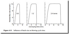
When steady state conditions are reached these will prevail regardless of the batch size, and so if an additional quantity of material is to be conveyed it will only influence the duration of the steady state stage. If the batch size was doubled, for example, to 1.2 tonne the extra 0.6 tonne would all be conveyed at the steady state rate, and so in a case where this was 12.3 tonne/h, it would only take a further 2.93 min to convey the additional material.
In Figure 4.11 the influence of batch size on the blowing cycle time is shown for three batch sizes. This illustrates quite clearly the assumption made and the proced- ure for the analysis. With a 0.6 tonne batch of barytes conveyed over 100 m through a 53 mm bore pipeline the ratio was 0.5. If the batch size is doubled the ratio will increase to 0.67, and if it is doubled again to 2.4 tonne the ratio will increase to 0.80.
Blow tank filling
It should be noted that the time for the filling of the blow tank and valve setting has not been taken into account in the above analysis, for the time is quite clearly not influenced by any of the variables associated with the blowing cycle, except for batch size. The average time taken to fill the blow tank with 0.6 tonne of barytes from the hopper above was about 10 s. If a time allowance based on this is added to the blowing cycle time, together with an allowance of 3 s for each valve setting operation, an estimate of the overall conveying cycle time can be obtained.
Conveying distance
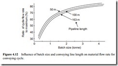
The result of an analysis of this type, for the complete cycle, is presented in Figure 4.12. From this it can be seen that batch size can have a significant effect on the cycle. The improvement with respect to batch size, however, increases at a decreasing rate. Conveying distance will clearly have an influence on the value of the ratio, for with longer lines there is a larger volume both to pressurize and de-pressurize. In the work with barytes it was found that the ratio for a 0.6 tonne batch conveyed through a 53 mm
bore line was about 0.54 for a 50 m long pipeline, and 0.46 with a 163 m long pipeline. The results of a similar analysis for these pipelines are also presented in Figure 4.12.
Pipeline bore
With the barytes, tests were additionally carried out on 50 m long pipelines of 81 and 105 mm bore. The mean value of the ratio for the 81 mm bore pipeline, for which the batch size was increased to 1.2 tonne, was 0.65; and for the 105 mm bore pipeline, for which the batch size was 1.4 tonne, it was 0.66. These values, which allow for blow tank filling and valving times, correspond very closely to those predicted by the curve on Figure 4.12, and so it is possible that pipeline bore has little additional effect.
Blow tanks with a discharge valve
The ratio of the mean flow rate to the steady state material flow rate can be improved by reducing the time required for some of the stages in the conveying process.
Blow tank pressurizing
If there is a valve on the blow tank discharge line, and control valves on the supplementary and fluidizing air supply lines, the blow tank can be pressurized in a shorter space of time if all the air available is directed to the blow tank, and discharge is prevented until the steady state pressure is reached. This time can be shortened further if an additional air supply is available for the purpose, but the cost and complexity would be consider- able, and the benefit obtained would probably be marginal.
When the blow tank discharge valve is opened the control valves on the supplementary and fluidizing air supply lines must be returned to their settings for conveying. This is essential, for the correct air flows must be maintained to achieve satisfactory blow tank discharge and material conveying at the desired rate. In the blow tank without a discharge valve these settings are never changed, and this is why it takes so long to achieve steady state conveying, particularly if the material is conveyed in dilute phase.
Blow tank venting
If there is a vent line between the blow tank and the supply hopper it will also be possible to reduce the time required for de-pressurizing the system. As soon as the blow tank is empty, the discharge valve should be shut and the vent line opened. It will also be neces- sary to shut the blow tank fluidizing air supply valve and fully open the supplementary air supply valve. By this means the blow tank can be isolated from both the air supply and the conveying line, and the processes associated with each can be carried out simultaneously.
By this means the blow tank can be de-pressurized very quickly in isolation from the conveying line. The total air supply will still be available to the pipeline so that this can be purged separately, and at the same time. This will also prevent the large volume of air in the blow tank from expanding rapidly through the conveying line, thereby causing very high air velocities and possible severe pipeline erosion during the venting process if the conveyed material is abrasive.
Isolation of the blow tank will also reduce the loading on the filtration unit at this time in the conveying cycle. It is important that this surge of air at the end of the cycle is taken into account when sizing the filters for the plant, regardless of the mode of blow tank operation, but particularly if the blow tank is not vented in isolation. If the blow tank is vented to the supply hopper it is equally essential that the filter on the supply hop- per is also correctly sized for the anticipated volumetric flow rate.


