High pressure conveying – Part I
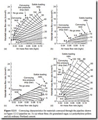
If high pressure air is available for conveying a material, and the pipeline is not too long, then the material could be conveyed in dense phase if the material is capable of being conveyed in dense phase. Conveying data for a group of four materials are presented in Figure 12.11. All four materials were conveyed through the same pipeline and this group of materials clearly illustrates the similarities and differences in conveying mode and capability when different materials are conveyed with high pressure air.
The compressor used for this high pressure work was capable of delivering 5.7 m3/min
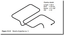
of air at 7 bar gauge. A high pressure top discharge blow tank, also rated at 7 bar gauge, with a fluidizing membrane, was used to feed the materials into the pipeline. All four materials were conveyed through the same pipeline, a sketch of which is given in Figure
12.12. These four materials show three very different types of behaviour in pneumatic conveying pipelines. That dense phase conveying is possible is clearly demonstrated with the flour and the cement. Air pressures up to 3.4 bar were utilized and solids load- ing ratios well in excess of 100 were achieved. The minimum conveying air velocity for these two materials was about 3 m/s.
The conveying limit for these two materials has an interesting shape. At low pressures, and hence low solids loading ratios, it has a positive slope, characteristic of that for dilute phase conveying. As both pressure and solids loading ratio increase, the slope reverses. Although the compressibility effect of pressure tends to maintain the positive slope, the solids loading ratio influence on minimum conveying air velocity (see Figure 11.7b) has an over-riding effect. At higher values of solids loading ratio, compressibility takes over once again.
Wheat flour
Conveying characteristics for wheat flour are shown in Figure 12.11a and it will be seen that the material could be conveyed in dense phase. Although the mean particle
size was about 90 j.Lm it is the shape of the particles for this mean particle size that gives the material the necessary air retention that allows it to be conveyed in dense phase and at low velocity. The bulk density of the material was about 510 kg/m3 and the particle density 1470 kg/m3.
Although solids loading ratios of 100 were achieved, and conveying was possible with pick-up velocities below 3 m/s, this was only in the area of low material flow
rates. The data above this area is truncated as a consequence of the discharge charac- teristics of the blow tank employed with this particular material. Blow tank discharge characteristics for this wheat flour conveyed from this particular blow tank were pre- sented in Figure 4.15a. It is fully expected that the material will convey successfully at much higher values of solids loading ratios and with much lower values of conveying line inlet air velocity with conveying line pressure drop values above 1.2 bar.
Granulated sugar
Conveying characteristics for granulated sugar are shown in Figure 12.11b and it will be seen that the material has no dense phase conveying capability at all. The maximum value of solids loading ratio achieved was only just above 15 and the minimum value of conveying line inlet air velocity was 16 m/s. The mean particle size of the sugar was about 460 j.Lm and although it is manufactured to have as narrow a size distribution as possible, the material does not have the permeability necessary for it to be conveyed in the plug flow mode of dense phase conveying. The bulk density of the material was about 890 kg/m3 and the particle density was 1580 kg/m3.
The conveying characteristics for the granulated sugar are positioned alongside those for the flour since in food and confectionary plant there is often a need for these two materials to be conveyed in the same system. The conveying capabilities of the two materials, however, are very different and there is no obvious solution to the problem. A review of the possibilities is presented in Chapter 19 where multiple use systems are considered in general.
Polyethylene pellets
The polyethylene pellets tested had a mean particle size of about 4 mm and were essentially mono-sized. As a consequence the material could be conveyed very well in dense phase flow and at low velocity. Tests were carried out with conveying line inlet air velocities down to 3 m/s and it is quite possible that the velocity could have been
reduced further without risk of blocking the pipeline. As can be seen from the con- veying characteristics, however, material flow rates are so low that it is unlikely to be economical to convey the material at such a low velocity. The bulk density of the material was about 540 kg/m3 and the particle density 912 kg/m3.
Despite the fact that high pressure air was available the maximum value of solids loading ratio was little more than 25. This was due to the fact that the material was so permeable. When viewed through sight glasses in the pipeline short plugs of material separated by air gaps were clearly visible. These characteristics are considered further in the next chapter.
Ordinary Portland cement
Cement, with a mean particle size of about 14 j.Lm is an obvious candidate for dense phase conveying in sliding bed flow. Very much better blow tank discharge character- istics were obtained and so solids loading ratios of over 100 were obtained at much higher values of conveying line pressure drop.
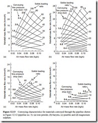
Conveying characteristics for another group of four materials conveyed through pipeline no. 3 with the top discharge high pressure blow tank are presented in Figure 12.13.
Iron powder
The conveying characteristics for iron powder, presented earlier in Figure 12.3b for low pressure dilute phase conveying, are shown again in Figure 12.13a for the high pressure conveying system. The difference between the two sets of data is quite remarkable and clearly illustrates the need for such test work to be undertaken. With the low pressure air a solids loading ratio of only six could be achieved, yet values of up to 120 are shown in Figure 12.13b. If the data is compared with that for the flour in Figure 12.11a it will be seen that for given conveying conditions, material flow rates achieved with the iron powder are higher than those achieved with the flour despite the differences in density values.
Barytes
Barytes was also presented earlier, in Figure 12.7b, and from the high pressure con- veying characteristics it will be seen that the conveying performance is similar to that of the iron powder, although material flow rates are significantly better with the barytes. With solids loading ratios above about 80 with this material the conveying line inlet air velocity is down to 3 m/s. With the nature of these conveying characteris- tics, however, the highest material flow rates are achieved with the lowest conveying air velocities.
Pearlite
Pearlite was also considered in the low pressure conveying group of materials and, as will be seen from Figures 12.12 and 12.13c, it will convey in dense phase and at low velocity. Material flow rates and hence solids loading ratios are much lower than those
for the flour, cement, barites and iron powder, but conveying line pressure drop values are also much lower. It is believed that this limit is caused by the exceptionally low value of bulk density with this material and that it was probably a combination of blow tank discharge and pipeline conveying capabilities. For given values of conveying line pressure drop, material flow rates achieved with the pearlite are greater than those for the previous materials considered.
Magnesium sulphate
Conveying characteristics for magnesium sulphate are presented in Figures 12.12 and 12.13d and this is clearly the poorest performing material of all those considered so far. That high pressure is not synonymous with dense phase conveying is clearly shown with this material. It was a granular material and so had no natural dense phase conveying capability. Provided that the minimum conveying air velocity was kept above a value of about 14 m/s, however, the material would convey very well, but it must be recognized that the material does require a relatively high velocity and that the resulting flow rate of the material will be lower than that of most other materials. This does reinforce the point that is constantly being made that a very wide range of con- veying capabilities exists and so materials must be tested for the purpose of system design.
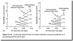
Conveying characteristics for another two materials conveyed through pipeline no. 3 with the top discharge high pressure blow tank are presented in Figure 12.14.
Alumina
Low pressure conveying characteristics for alumina were presented in Figure 12.6. High pressure conveying characteristics for a calcined alumina are given in Figure 12.14. The minimum conveying air velocity was about 15 m/s and so as only 5.7 m3/min
(0.116 kg/s) of air was available the maximum conveying line pressure drop that could be utilized was only 1.4 bar. This data confirms the statement made at Section 12.2.2.1 that this material, although having a relatively small mean particle size, will not con- vey in dense phase even if a high pressure is available. The mean particle size for this particular material does need to be much smaller for dense phase to be possible with a conventional conveying system.
Conveying characteristics for zircon sand are presented in Figure 12.14b. Zircon sand has a mean particle size of about 120 j.Lm with a fairly narrow particle size distribution and as a consequence has very poor air retention properties. It would only convey in dilute phase suspension flow and required a minimum conveying air velocity of about 14 m/s. The bulk density of the material was about 2600 kg/m3 and the particle density was 4600 kg/m3. This provides confirmation once again that high density materials pres- ent no problem with respect to pneumatic conveying and that at these particle sizes, den- sity appears to have little influence on the minimum value of conveying air velocity.
Comparison of materials – flow rate
As a large number of different materials have been conveyed through pipeline no. 3, the 1.5 bar pressure drop lines have been taken from a representative number and plot- ted on a separate graph. This is presented in Figure 12.15 and illustrates the differences between the conveying capabilities of the different materials very well.
Every material presented is capable of being conveyed in dilute phase and Figure 12.15 illustrates the differences that can exist with this group of nine materials. With a conveying line inlet air velocity of 16 m/s granulated sugar only just gets on this plot but it does illustrate where the dilute phase conveying region is on the graph. At high velocity all the curves are now sloping down towards the horizontal axis, and hence zero material flow rate, and each one will probably reach the air flow rate axis at a value of about 0.45 kg/s (see Equation (10.21)). For dilute phase conveying, therefore, there is approximately a 2:1 spread in terms of material flow rate achieved for identical conveying conditions in this common pipeline.
At the low velocity end of this plot it will be seen that there is approximately a 20:1 spread in terms of material flow rate achieved for identical conveying conditions. The polyethylene pellets is the only material in this group capable of being conveyed in the
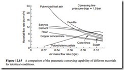 plug flow mode of dense phase conveying but is typical of this group of materials. The PF ash (fly ash), barytes, cement and wheat flour are all in the sliding bed category of dense phase conveying capability and this plot illustrates the spread in capability that can exist with this group of materials at low values of conveying air velocity. It is suspected that the pearlite is limited because of its extremely low value of bulk density.
Conveying characteristics for the copper concentrate and the coke fines are presented in Figure 12.16.
Copper concentrate
The copper concentrate is one of those materials that is on the borderline of dense phase conveying but just does not have sufficient air retention capability. The mean particle size was about 55 j.Lm and had a fairly narrow size distribution. With high pressure air it could be conveyed down to a minimum conveying air velocity of about 8 m/s but no lower. As a consequence the maximum value of solids loading ratio was about 45. The copper concentrate had a bulk density of about 1660 kg/m3 and a parti- cle density of 3950 kg/m3.
Coke fines
The coke fines, presented in Figure 12.16b, are a petroleum coke derivative and had a mean particle size of about 800 j.Lm with a fairly wide particle size distribution. The minimum conveying air velocity for the material was about 13 m/s. Compared with
the sugar the material flow rate for the coke is slightly higher and the minimum velocity slightly lower. As a consequence a solids loading ratio of about 25 was achieved, but this is still very much dilute phase conveying and is only high because of the very high pressure gradient available with a two bar pressure drop in the 50 m long pipeline.
Comparison of materials – conveying limits
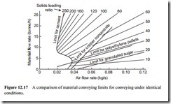
Conveying limits in terms of minimum conveying air velocities and maximum solids loading ratios vary widely for different materials. This point is clearly illustrated in Figure 12.17 with the limits for four representative materials presented. Each material was conveyed through the 50 m long pipeline no. 3 of 53 mm bore in a full programme of tests.
Fly ash
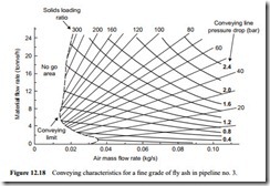
In Figure 12.10 the low pressure conveying characteristics for a fine grade of pulverized fuel ash (fly ash) were showing very definite signs of the transition to dense phase conveying capability at high values of pressure drop. The conveying characteristics for this same material conveyed through pipeline no. 3 (Figure 12.12) are presented in Figure 12.18.
For dilute phase conveying the minimum conveying air velocity is about 11 m/s and in Figure 12.18 this is represented at the very bottom of the conveying characteristics. As explained above, this is in an insignificant area of these high pressure conveying characteristics. With a minimum conveying air velocity of about 3 m/s, once the solids loading ratio is above about 80, and constant pressure drop lines that always have a negative slope, very high values of solids loading ratio can be achieved without unduly high air supply pressures in such a short pipeline.
Certain grades of fly ash can be conveyed quite successfully at very much lower values of velocity than those reported here, but at these very low velocities there is a
tendency for the slope of the constant pressure drop lines to change from negative to positive. Great care must be exercised with fly ash because there are an infinite num- ber of grades and they all potentially have different conveying characteristics [2].
