Single blow tank control
With rotary valves and screw feeders, material flow rate can be controlled, over a limited range, simply by varying the drive speed. Blow tanks, as already mentioned in Chapter 3, have no moving parts, and yet turn-down ratios of 10:1 can be achieved quite successfully.
Air proportioning
Control of a blow tank is achieved by proportioning the total air supply between that which is directed to the blow tank and that which goes directly to the start of the conveying line. The total air supply is used to convey the material through the pipeline.
Blow tank air
The air directed to the blow tank is used to pressurize the blow tank. This air supply may also aerate or fluidize the material, depending upon the bulk characteristics of the material. The blow tank air discharges the material from the blow tank into the convey- ing line. The solids loading ratio of the material in the blow tank discharge line can be extremely high, and hence there is a pressure drop associated with this feeding. This is why supplementary air is necessary, unless the conveying line is very short and high pressure air is available.
Supplementary air
The supplementary air passes directly to the start of the conveying line at the blow tank discharge point. The supplementary air effectively dilutes the flow of material for
conveying through the pipeline. It is essential that the correct solids loading ratio is achieved at this point in order to match the capability of the air mover in terms of pressure available. If the solids loading ratio is too low, for example, the pressure drop over the conveying line will be low and the pipeline will be under-utilized. If, on the other hand, the solids loading ratio is too high, the pressure drop required for conveying the material through the pipeline may exceed the capability of the air mover, and the pipeline will probably block.
Discharge rate control
Figure 3.28 was presented to show how the proportion of air that is used to fluidize the material in the blow tank can influence the discharge rate. The discharge characteristics presented are essentially a graph of material flow rate against total air mass flow rate, with data in terms of the ratio of fluidizing air to total air mass flow rate superimposed.
The influence of blow tank type
Both top and bottom types of blow tank are used in industry but the choice of configuration is often based on convenience rather than the merits of configuration and performance. In a programme of work carried out for the original Design Guide the performance of a blow tank, capable of being arranged in either top or bottom dis- charge, was compared with these two configurations [1].
A sketch of the two blow tank systems is given in Figure 4.13. The bottom section of the blow tank vessel was constructed so that it could be changed and either a mem- brane or a bottom discharge section could be used. In both cases the conveying line was identical, apart from slight changes at the start to accommodate differences in blow tank geometry.
Conveying line performance
The first point to note with respect to the differences between top and bottom dis- charge from blow tanks is that there is no difference in conveying line performance between the two. For a given material and pipeline, the conveying characteristics pro- duced were identical such that for a given air flow rate and conveying line pressure drop the material flow rates were identical for the two blow tank systems.
This is perhaps not surprising since if a material is continuously fed into a pipeline there is not likely to be a difference in performance, regardless of the method by which the material was fed, provided that it is reasonably steady and continuous. Only if the material is pulsed into the pipeline, as with the pulse phase system of Figure 2.11 would a marked difference in performance be expected.
Blow tank discharge performance
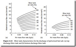
As part of the research programme, the discharge characteristics of the two blow tank configurations were compared for the same material and the same pipeline. Extensive tests, therefore, were carried out with a fine grade of pulverized fuel ash conveyed through a 53 mm bore pipeline, 50 m long, containing nine 90° bends. In the top dis- charge mode material flow rates of up to 24 tonne/h were achieved, but in the bottom discharge mode this was almost halved. The two sets of blow tank characteristics are shown in Figure 4.14 for comparison.
There are three limits on these two plots. The one on the left, at low air flow rates, represents the minimum conveying limit for the material. This relates to the air flow rate necessary to achieve the minimum value of conveying air velocity. The two plots are very similar in this respect, as would be expected. The limit to the right, at high air flow rate, is simply set by the volumetric capability of the compressor used to supply
the air. The limit at high material flow rates, with all the air directed into the blow tank, represents the maximum discharge capability of the blow tank for the material being discharged.
It was mentioned at the end Section 4.4.1.1 above that as a generalization, the top discharge blow tank, with fluidization of the material, is most suitable for powdered materials. This would tend to be confirmed with Figure 4.14. It is suspected, however, that if fluidizing air was introduced more efficiently in the bottom discharge blow tank case, an improvement in performance would be obtained. This, however, would prob- ably involve introducing a separate source of air into the centre of the flow with an aerated nozzle and this may cause obstruction by its presence. The work clearly demonstrates that blow tanks will work, but the discharge capability is not readily predictable.
The 100 per cent line on the blow tank characteristics represents the discharge limit of the blow tank. If a higher discharge rate is required from a blow tank, an improve- ment in the aeration of the material might help. Otherwise a larger discharge pipe will be needed. The discharge pipe does not have to be the same diameter as the conveying pipeline.
Material discharge performance
It is well known that different materials can have different conveying characteristics when conveyed through exactly the same pipeline, and this will be considered in detail in Chapter 12. The same also applies in terms of different materials with respect to their blow tank discharge characteristics. The property values of some materials tested in the top discharge blow tank are presented in Table 4.1 for reference.
Each of the materials presented in Table 4.1 was conveyed from the top discharge blow tank shown in Figure 4.13 and was conveyed through the 50 m long pipeline of 53 mm bore. The blow tank characteristics for the pulverized fuel ash were presented earlier in Figure 4.14a and those for the other four materials are presented in Figure 4.15. The materials considered cover a wide range of both densities and particle sizes. The materials show considerable diversity in their discharge characteristics and illustrate the difficulties of blow tank control. Fortunately most blow tanks are dedicated to a single material and so can readily be adjusted for the given material on commissioning.
The discharge characteristics for the granulated sugar and polyethylene pellets illustrate the problems of top discharge for granular materials compared with fine
powdered materials. This is particularly the case with the sugar where control is over a limited proportion of blow tank air.
Blow tank control systems
If a blow tank is required to convey a variety of materials, or just one material over a range of distances, so that the material flow rate will need to be changed, an automatic control facility would be essential. Air supply pressure is the controlling parameter and so some form of feedback control should be provided on the air supply to the blow tank to ensure that the conveying line always works to the maximum capacity that the air supply pressure will allow.
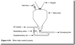
The most effective way of controlling the blow tank discharge rate is to provide a modulating valve on one of the air supply lines. This will automatically proportion the total air supply between the blow tank and the supplementary line. A sketch of such
a system, fitted to a bottom discharge blow tank, is shown in Figure 4.16. In this case the feedback signal is from the air pressure in the supplementary air supply line.
If the pressure monitored is below the operating value for the system, the modulating valve will restrict air flow to the supplementary line and so more will be directed to the blow tank. With a greater proportion of the air supply directed to the blow tank, the feed rate will increase. If the pressure rises too much, the modulating valve will open a little to allow more supplementary air, and hence the material flow rate will be reduced.
This type of control is particularly useful on the start-up and tail-out transients associated with the conveying cycle. During start-up, for example, all the air will be automatically directed to the blow tank to effect a rapid pressurization, and control will automatically be achieved with lines of different length. The sensing device for the valve is often positioned in the supplementary airline rather than in the air supply line. In the supplementary airline, changes in pressure will be monitored very quickly. In the air supply line the blow tank has a damping effect and consequently there will be a slight delay in sensing pressure changes.


