Fine material
Introduction
Pneumatic conveying systems are usually designed on the basis of scaling available data. This may come from an existing plant pipeline in which the identical material has been conveyed, and conveying data has been obtained. Alternatively the data will be obtained from a test facility in which the required material will have been conveyed, specifically to obtain test data.
From an existing plant pipeline it is quite likely that just a single data point will be obtained, for there is generally little scope for varying either air or material flow rates. With a test facility air and material flow rates can generally be varied widely, as well as conveying line pressure drop, and instrumentation would be available for the meas- urement of all of these parameters.
It is most unlikely, however, that sufficient data would be taken so that full sets of conveying characteristics could be drawn. For most systems manufacturing com- panies this would be an unnecessary and expensive luxury. Relatively few tests would be carried out under chosen conditions that would scale to the required material flow rate for the type of system that the company would want to supply to a customer. If this is a dense phase design they would clearly establish that the material had the necessary conveying capability as part of the test procedure.
Dense phase conveying of cement
To illustrate the scaling process for system design with regard to dense phase convey- ing, ordinary Portland cement has been selected. This is a material that, by virtue of its mean particle size and particle shape, conveys very well in dense phase at low velocity. It is a major bulk commodity on a worldwide scale and because of its size it is gener- ally conveyed by pneumatic conveying systems. A considerable number of countries manufacture cement and several produce more than 100 million tonne/year. The UK manufactures about 20 million tonne/year and is about twentieth in the ‘league’. It is not just in manufacturing plants that it requires conveying. It is distributed to depots by road, rail and sea.
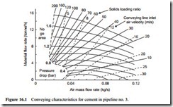
To illustrate the system design process just a single point on the conveying characteristics is taken. If it should be required to scale the whole or part of the conveying characteristics, as was illustrated in Chapter 14 on ‘Pipeline scaling parameters’, it is simply a matter of repeating the process. For this purpose a grid could be drawn on the
conveying characteristics to be scaled and the value for each grid point evaluated so that a set of conveying characteristics can be constructed for the required pipeline.
