Conveying data
Conveying data for cement conveyed in a conventional pneumatic conveying system was presented in Figure 13.3. It is this data that is to be used in the scaling process and so is reproduced in Figure 16.1 for reference. The conveying system used to generate the data employed a high pressure blow tank for feeding material into the pipeline. This type of feeder is ideal for abrasive materials such as cement since it has no moving parts and is capable of achieving the wide range of conveying conditions required.
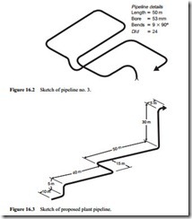
The test pipeline used was about 50 m long, 53 mm bore and incorporated nine 90° bends. It was almost entirely in the horizontal plane. This is pipeline no. 3 from Figure 12.12 and is reproduced here in Figure 16.2 for reference.
Conveying duty
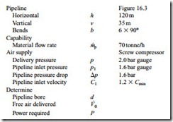
It is suggested that a design should be considered for the conveying of the cement over a distance of about 155 m at a rate of 70 tonne/h and that a screw compressor with a 2 bar gauge rating should be used. A sketch of the proposed pipeline is given in Figure 16.3.
The pipeline routing includes a total of 120 m of horizontal pipeline and a total of 35 m of pipeline in which the material is conveyed vertically up. Six 90° bends are incorporated in the pipeline. A steel pipeline is proposed.
Conveying capability
The equivalent length of bends was considered in Section 14.5 and data for 90° bends having a D/d ratio of 24:1 was presented in Figure 14.16. It was also shown in Section
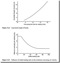
14.5 that the D/d ratio had little effect on equivalent length for D/d ratios between about four and forty. It is suggested that radiused bends would be used and Figure 14.16 is reproduced here in Figure 16.4 for reference. It is believed that this relation- ship is influenced by material type but that this data provides a reasonable average. For materials having a high coefficient of restitution the equivalent length will be lower, but it will be higher for materials such as wheat flour, as considered in Section 14.5.
Cement, as will be seen from Figure 16.1, is capable of being conveyed in dense phase and at low velocity. The potential influence of solids loading ratio on the minimum conveying air velocity was first presented in Chapter 11 with Figure 11.7b. The influence of this relationship on the scaling of the conveying characteristics was considered in Chapter 13. Data specifically for ordinary Portland cement was presented in Figure 13.5 and so this is reproduced here in Figure 16.5 for reference. A similar relationship between minimum conveying air velocity and solids loading ratio holds for all materials capable of being conveyed in dense phase in sliding bed flow. There will, of course, be
slight variations in the dilute phase conveying limit and the transition to full dense phase conveying capability, as illustrated on Figure 13.5, for other materials.
The design is based on the use of a conveying line inlet air velocity 20 per cent greater than the minimum value as recommended. It is suggested that the design be based upon achieving the 70 tonne/h with a conveying line pressure drop of 1.6 bar. The diameter of pipeline needed to achieve the given duty has to be established first. The volumetric flow rate of air required then needs to be determined for specification of the compressor, together with the power required for the drive motor.


