Industrial solutions and practical issues
To a certain extent the problem of bend wear in pneumatic conveying system pipelines is a problem with which industry has learnt to live. There are a number of ways by which the severity of the problem can be reduced, but a number of factors relating to the material conveyed and the system itself have to be taken into account. Expense is obviously a consideration, some methods may lead to a reduction in the conveying capability of the plant, and if the material being conveyed is friable then a solution that minimizes the effect of degradation must be sought.
Pipeline considerations
The volumetric flow rate of air specified and the pipeline bore chosen are of major importance, for the two have to be selected so that the resulting conveying air velocity is acceptable. The problem is that air is compressible and so its value is significantly affected by pressure. This represents a particular difficulty in high pressure systems, where the air pressure can drop from several bar at the start of the pipeline to atmos- pheric at the other end. As the pressure of the conveying air decreases along the length of the pipeline its density decreases, with a corresponding increase in volumetric flow rate, and hence velocity. In order to keep the velocity to within reasonable limits, stepped pipelines are often employed. A similar situation exists with negative pressure systems when operating under high vacuum. These issues were considered in detail in Chapter 9.
If, for example, the air supply pressure in a positive pressure conveying system is 3 bar gauge, and the conveying line inlet air velocity is 15 m/s, the conveying air velocity will approximately quadruple to about 60 m/s at the end of the pipeline in a single bore line. A 4-fold increase in velocity will result in an almost 40-fold increase in mass eroded from the bends. This explains why bends near the end of a pipeline will generally fail in a much shorter time than those near the start of the pipeline. If a dense phase sys- tem was specifically installed to overcome the problem of erosion, a stepped pipeline for such a system would be almost essential if a high air supply pressure was used.
Bend wear
By the very nature of the transport process, pipelines used for pneumatic conveying systems are prone to wear when abrasive materials have to be conveyed. In dilute phase, materials are conveyed in suspension in the air, and a high conveying air vel- ocity must be maintained in order to keep the material moving, and so avoid pipeline blockage. The main problem relates to the wear of bends in the pipeline, and any other surfaces where particles are likely to impact as a result of a change in flow direction. Bends provide pneumatic conveying systems with their flexibility in routing, but if the material is abrasive and the velocity is high, rapid wear can occur.
Influence of bend geometry
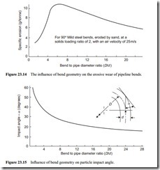
Bends are available in a wide range of geometries, in terms of bend curvature, from long radius bends to tight elbows and mitred bends. As bends are so vulnerable to wear there have been many developments and innovations for reducing the problem. The author has investigated the influence of bend geometry [17]. A wide range of D/d values were investigated and the results for 90° mild steel bends are shown in Figure 23.14. The bends were eroded by sand, conveyed at a solids loading ratio of two and with a conveying air velocity of 25 m/s .
The results can, to a certain extent, be predicted from the data presented in Figure 23.1 on the influence of impact angle on erosive wear for a ductile material. With sharp bends, having a low D/d ratio, the majority of the particles will impact against the bend wall at a fairly steep angle. At a high impact angle erosive wear will not be too severe for a duc- tile material and so it can be expected that the bend will not wear too rapidly.
A bend with a D/d ratio of about 6:1 corresponds closely to the worst case from the data in Figure 23.14. The majority of the particles will impact against the bend wall at an angle of about 20°. For a ductile material this will result in maximum erosion and so the bend can be expected to fail quickly. Particle impact against the wall for bends
with a D/d ratio greater than about 20:1 is at a much shallower angle. If the impact angle is relatively small the erosion will not be too severe, and so for this case also it can be expected that the bend will not wear too rapidly.
Long radius bends
A very low impact angle is an essential pre-requisite for minimizing erosion, particu- larly in the case of brittle surface materials. In the case of ductile materials, because of the remarkably steep increase in erosion with very small increase in impact angle, as shown in Figure 23.1, exceptionally long radius bends would be required. It is possi- ble to calculate the relationship between the bend geometry (D/d ) and the impact angle. The results of such an analysis are given in Figure 23.15 and this clearly shows the nature of the problem.
For ductile materials long radius bends are not likely to be a viable proposition. For brittle materials, however, such as basalt and cast iron, they are essential, as mentioned above. A common method of providing a long radius bend is to make the bend in seg- ments. By this means the bend will be lighter and much easier to fit into the pipeline. Since the majority of the wear will be at the primary impact point only one or two sec- tions need to be replaced should the bend fail. It is also possible to reverse and inter- change segments and so extend the overall life of the bend. Segments can be made in 45°, 30° and 221⁄2° sections. A four section long radius bend is shown in Figure 23.16a.
Short radius bends
With very short radius bends the angle at which the material impacts against the bend wall will be fairly high, as shown in Figure 23.15. Although this will not be suitable for brittle surface materials, ductile materials, because of their improved erosion resistance at high impact angle often gives reasonable service in use, if the conveyed materials is not too abrasive.
Three major problems have to be taken into account, however, before using very short radius and similar bends. The more severe the impact of the material against the bend wall the greater will be the problem of degradation if the material is friable (see Chapter 24). The introduction of a very short radius bend will probably also increase the conveying line pressure drop, which will mean that the material mass flow rate will have to be reduced to compensate (see Section 14.5.2). A very short radius bend, and those that are designed to trap the conveyed material, may require a slightly higher value of conveying line inlet air velocity to ensure that the pipeline does not block.
A very cheap and often effective solution to the erosion problem is to use a blanked tee-piece or mitred bend (D/d = 0). Such a bend is shown in Figure 23.16b. This gives a simple right-angled bend in the line, and so consideration has to be given to even greater problems of added degradation and pressure drop. The material being con- veyed, however, fills the blanked section of the tee and part of the bend so that much of the material being conveyed impacts against itself and not against the pipe wall.
Should the line block at the bend, access can easily be gained from the blanked section to facilitate clearing.
A more sophisticated version of this was developed about 30 years ago and is known as the Booth bend after its originator. This is a very short radius cast bend which incorp- orates a shallow depression. This allows material to collect in the bend and so subse- quent material flowing through the pipeline will impact against itself. A sketch of the bend is given in Figure 23.17a.
Another more recent version is a short radius bend with a large recessed chamber in the area of the primary wear point. It is claimed that this acts as a vortice and that mater- ial is constantly on the move in this pocket, thereby providing a cushioning effect. Consideration, however, has to be given to the orientation of the bend. A sketch of the bend is given in Figure 23.17b.
Air injection
A number of bend protection devices have been proposed that incorporate the injection of air into a bend. The object of these is to deflect the impacting particles away from the bend wall. The main problem with this type of device in a pneumatic conveying line is that air injection has to be continuous at each bend. In a pipeline of constant bore this will result in a further increase in velocity, and since erosion is highly dependent upon velocity, this method does tend to aggravate the problem. The pipeline can be stepped to a larger diameter part way along its length to compensate, but this adds considerably to the cost of the plant and the complexity of its design, and so this method is rarely used.
The use of hard materials
Hard, brittle materials are generally used in cases of severe wear. Materials used include Ni-hard, basalt and ceramics, as discussed in Section 23.2.5.3. These materials can gen- erally be cast or formed into sections, and in the case of non-metals, are used for lining pipes and bends. Care must be taken with cast materials, however, as mentioned above
in relation to Surface Finish at Section 23.2.8, for if a porous surface if obtained, rapid erosion can result.
The use of resilient materials
Resilient materials such as rubber and polyurethane are widely used in erosive wear situations. Although the hardness of the surface is often far lower than that of the material being conveyed, and impacting against the surface, they derive their erosive wear resistance from the fact that they are able to absorb much of the impact energy, without being permanently damaged, by virtue of their resilience, as mentioned earlier.
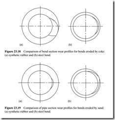
The author has carried out several programmes of tests to compare rubber and steel bends [18]. In one such programme a pipeline was built in which several rubber and steel bends were alternately positioned at the corners of a test loop so that they could be tested at the same time for a direct comparison. Tests were carried out with lump coke and fine silica sand, each conveyed at a solids loading ratio of 10 and with a con- veying air velocity of about 25 m/s. Figures 23.18 and 23.19 show the comparative wear effects of the coke and sand on the rubber and steel bends very well.
These are pipe section profiles taken at the point around the bend where either the bend failed or where the penetrative wear was a maximum. Each bend was 53 mm bore, with a pipe wall thickness of 4 mm in the case of the steel bends and 10 mm in the case of the rubber bends. To illustrate the different erosive wear profiles the pipe wall has been magnified by a factor of 1.5 in relation to the pipe bore.
Figure 23.18 compares the pipe section profiles of the steel and rubber bends when eroded by coke. The rubber bends failed after 50 tonne of coke had been conveyed through them, at which time about 56 g had been eroded from the bends. Only 32 g has been eroded from the steel bends, however, and they would probably be capable of conveying another 50 tonne before they would fail. In terms of potential service life, therefore, the 4 mm thick steel bends could be expected to last twice as long as the 10 mm thick rubber bends for the conveying of the coke.
Figure 23.19 compares the pipe section profiles of the steel and rubber bends when eroded by the sand. In this case the steel bends failed after only 3.5 tonne of the sand had been conveyed through them, at which time about 54 g had been eroded from the bends. Only 10 g was eroded from the rubber bends at this stage, and they were quite clearly capable of handling considerably more sand before they would fail. In terms of potential service life, therefore, the rubber bends could be expected to last about five times as long as the steel bends for the conveying of the sand.
Thus for bulk materials having a large particle size, such as lump coal, coke and mined and quarried products, rubber bends cannot be recommended for erosive wear applications. It is believed that there is a threshold value of impact energy that resilient materials such as rubber can withstand without suffering significant damage, as dis- cussed in the section on Resilient Materials above. As either particle size or impact velocity increase, the impact energy of a particle will increase. In relation to velocity this effect was shown quite clearly in Figure 23.12.
Surface coatings
A wide range of materials can be applied to existing surfaces, and in many cases they are applied to erosion resistant surfaces, such as Ni-hard, to give added protection. Polyurethane, which cures at ambient temperature, is often used. This can be sprayed, or applied in putty form by trowel, which is particularly useful for repairing eroded surfaces. Hardfacing metal alloys, tungsten carbide and a range of oxide ceramics can be applied to surfaces by means of flame spray coating. Some of these materials have very high hardness values, and combined with the fact that the surfaces can also be very smooth, they can provide good erosion resistance. The surface coatings, however, can generally be applied only in thin layers and so once this is penetrated the bend will rapidly fail.
Wear back methods
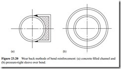
Wear back methods are potentially the cheapest and most effective means of sup- pressing erosion. A channel welded to the back of a bend and filled with concrete, as shown in Figure 23.20a, is probably the most common method adopted. When the outer surface of the original steel bend erodes, the concrete will generally extend the
life of the bend for a reasonably long time. It is essential however, that the wear back covers as much as possible of the outer bend surface, for bends can be holed over a wide range of both bend and pipe angles.
The only problem with this type of solution is that when a primary wear point is established in the concrete at the initial impact point, deflection of particles can result, and these may cause erosion of the inside surface of the bend. The bend may well fail through erosion of the inside surface long before the material has penetrated the con- crete. Secondary and tertiary wear pockets in long radius bends may also cause the material to be deflected against the wall of the following straight length of pipe and cause this to fail. These points are considered in more detail below. A similar method of prolonging bend life is to sleeve the main bend with another pressure-tight bend, which is shown in Figure 23.20b. When the inner bend fails the space will fill with the material being conveyed.
The use of inserts
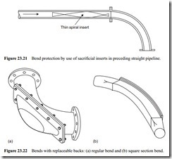
Considerable protection can be provided for a bend by positioning a sacrificial insert in the pipeline just prior to the bend. An insert made of a flat strip twisted through 180°, for example, and shown in Figure 23.21, will ensure that the material impacts against the insert prior to impact against the bend. The velocity of the particles will be reduced after impact with the strip and the presence of the strip will prevent the par- ticles from focusing on a small area of the bend. Such a strip should offer little resist- ance to flow and should last for a reasonable period of time, since the wear would be very evenly distributed over the entire surface of the strip [19].
Ease of maintenance
In terms of ease of maintenance, very short radius bends have the particular advantage of their much lighter weight. These can generally be removed and changed by two people without the use of special lifting equipment. Bends with the provision of replaceable
wear backs are also very useful in this respect, such as those shown in Figure 23.22, as the bend itself does not have to be removed or replaced.
For regular radiused bends, as shown in Figure 23.22a, the wear backs are usually made of Ni-hard or similar material. The backs must be replaced on a regular basis, however, and not when failure occurs. If they are left until failure occurs, much of the body may have worn away and it may not be possible to guarantee an air-tight seating. If the material being conveyed is potentially explosive, the possibility of this type of bend wearing to a point where it will be incapable of withstanding the explosion pres- sure generated must also be considered.
With large bore pipelines square section bends are often fabricated, and in such a manner that the outer wall can be removed, as illustrated in Figure 23.22b. This allows for easy replacement. Alternatively the backing plate can be made of a different mater- ial, or be given a lining of a costlier material, to resist the erosive wear.


