types of control valve
There are essentially three types of control valve: poppet valves, spool valves and rotary valves.
Poppet valves
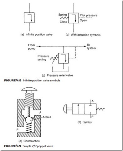
In a poppet valve, simple discs, cones or balls are used in conjunction with simple valve seats to control flow. Figure 4.9 shows the construction and symbol of a simple 2/2 normally closed valve, where depression of the pushbutton lifts the
ball off its seat and allows fluid to flow from port P to port A. When the button is released, spring and fluid pressure force the ball up again, closing the valve.
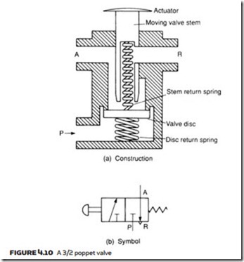
Figure 4.10 shows the construction and symbol of a disc seal 3/2 poppet. With the pushbutton released, ports A and R are linked via the hollow pushbut- ton stem. If the pushbutton is pressed, port R is first sealed, then the valve disc pushed down to open the valve and connect ports P and A. As before, spring and fluid pressure from port P closes the valve.
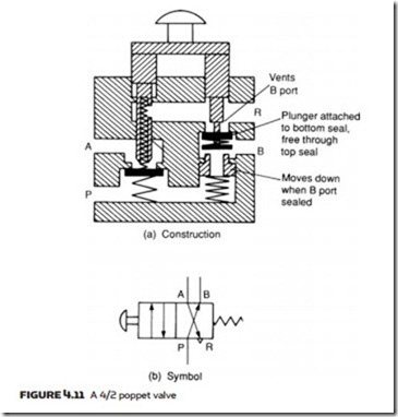
The valve construction and symbol shown in Figure 4.11 is a poppet change- over 4/2 valve using two stems and disc valves. With the pushbutton released, ports A and R are linked via the hollow left-hand stem and ports P and B linked via the normally open right-hand disc valve. When the pushbutton is pressed,
the link between ports A and R is first closed, then the link between P and B closed. The link between A and P is next opened, and finally the link between B and R opened. When the pushbutton is released, air and spring pressure puts the valve back to its original state.
Poppet valves are simple, cheap and robust, but it is generally simpler to manufacture valves more complicated than those shown in Figure 4.11 by using spool valves. Further, a major disadvantage of poppet valves is the force needed to operate them. In the poppet valve of Figure 4.10, for example, the force re- quired on the pushbutton to operate the valve is P × a newtons. Large-capacity valves need large valve areas, leading to large operating force. The high pressure in hydraulic systems thus tends to prevent use of simple poppet valves and they are, therefore, mainly found in low-pressure pneumatic systems.
spool valves
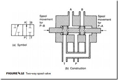
Spool (or slide) valves are constructed with a spool moving horizontally within the valve body, as shown for the 4/2 valve in Figure 4.12. Raised areas called ‘lands’ block or open ports to give the required operation.
The operation of a spool valve is generally balanced. In the valve construc- tion in Figure 4.12b, for example, pressure is applied to opposing faces D and E
and low tank pressure to faces F and G. There is no net force on the spool from system pressure, allowing the spool to be easily moved.
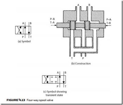
Figure 4.13 is a changeover 4/2 spool valve. Comparison of the valves shown in Figures 4.12 and 4.13 shows they have the same body construction, the only difference being the size and position of lands on the spool. This is a major cost- saving advantage of spool valves; different operations can be achieved with a common body and different spools. This obviously reduces manufacturing costs.
As a valve goes from one state to another the port connections will go through a transitional state. This temporary state may be important in some cases, for example the designers would not want a cylinder supporting a load to be con- nected to the tank even for a brief moment. If the transitional state is important the valve can be ordered accordingly and the transitional state shown on the diagram. Figure 4.13c shows that the transitional state, denoted by the dashed central lines, blocks all four ports. Note that although this is a two-position valve, with the inclusion of the transitional state it is shown by three blocks.
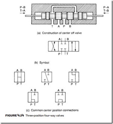
Figure 4.14 shows various forms of three-position changeover valves; note, again, these use one body with different functions achieved by different land patterns.
Spool valves are operated by shifting the spool. This can be achieved by button, lever or striker, or remotely with a solenoid. Self-centering can easily be provided if springs are mounted at the end of the spool shaft.
Solenoid-operated valves commonly work at 24 V DC or 110 V AC. Each has its own advantages and disadvantages. A DC power supply has to be pro- vided for 24 V DC solenoids, which, in large systems, is substantial and costly. Operating current of a 24 V solenoid is higher than that of a 110 V solenoid. Care must be taken with plant cabling to avoid voltage drops on return legs if a common single line return is used.
Current through a DC solenoid is set by the winding resistance. Current in an AC solenoid, on the other hand, is set by the inductance of the windings, and this is usually designed to give a high inrush current followed by low holding current.
This is achieved by using the core of the solenoid (linked to the spool) to raise the coil inductance when the spool has moved. One side effect of this is that a jammed spool results in a permanent high current which can damage the coil or the device driving it. Each and every AC solenoid should be protected by an individual fuse. DC solenoids do not suffer from this characteristic. A burned out DC solenoid coil is almost unknown.
Whatever form of solenoid is used it is very useful when fault finding to have local electrical indication built into the solenoid plug top. This allows a fault to
be quickly identified as either an electrical or hydraulic problem. Fault finding is discussed further in Chapter 9.
A solenoid can exert a pull or push of about 5–10 kg. This is adequate for most pneumatic spool valves, but is too low for direct operation of large-capacity hydraulic valves. Here pilot operation must be used, a topic discussed later.
rotary valves
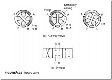
Rotary valves consist of a rotating spool which aligns with holes in the valve casing to give the required operation. Figure 4.15 shows the construction and symbol of a typical valve with center off action.
Rotary valves are compact, simple and have low operating forces. They are, however, low-pressure devices and are consequently mainly used for hand op- eration in pneumatic systems.
