Sequencing valve
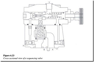
A sequencing valve again is a normally closed pressure control valve used for ensuring a sequential operation in a hydraulic circuit, based on pressure. In other words, sequencing valves ensure the occurrence of one operation before the other. A sectional view of a sequencing valve is shown in Figure 6.23.
When the components connected to port A of the valve reach the pressure set on the valve, the fluid is passed by the valve through port B to do additional work in a different portion of the system. The high-flow poppet of the sequence valve is controlled by the spring-loaded cone. At low pressures, the poppet blocks the flow of fluid from entering port A. The pressure signal at port A passes through the orifices to the top side of the poppet and to the cone. There is no flow through the valve unless the pressure at port A exceeds the maximum set pressure on the spring-loaded cone. When the pressure reaches the set valve, the main poppet lifts, allowing the flow to pass through port B. It maintains the adjusted pressure at port A until the pressure at port B rises to the same value. A small pilot flow (about 1A gpm) goes through the control piston and past the pilot cone to the external drain. When there is subsequent pressure increase in port B, the control piston acts to prevent further pilot flow loss. The main poppet opens fully and allows the pressures at port A and B to rise together. Flow may go either way during this condition.
Application
Let us consider a hydraulic circmt m which two cylinders are used to execute two separate operations as shown in Figure 6.24.
Now, let us assume that cylinder A is required to extend completely before cylinder B extends. This can be accomplished by placing a sequencing valve just before cylinder B as shown. The pressure value of the valve is set to a predetermined value say 28 kg/cm2 (400 psi). This ensures that the operation involving cylinder B will occur after the operation involving cylinder A or in other words, cylinder B will not extend before a pressure of 28 kg/cm2 (400 psi) is reached on cylinder A.
Counterbalance valve
A counterbalance valve again is a normally closed pressure control valve and is particularly used in cylinder applications for countering a weight or overrunning load. Figure 6.25 shows the operation of a typical counterbalance valve.
The primary port of this valve is connected to the bottom of the cylinder and the secondary port is connected to the direction control valve (DCV). The pressure setting of the counterbalance valve is kept higher than required to prevent the cylinder load from falling.
When the pump flow is directed to the top of the cylinder through the DCV, the cylinder piston is pushed downward. This causes the pressure at the primary port to increase and raise the spool. This results in the opening of a flow path for discharge through the secondary port to the DCV and back to the tank.
When raising the cylinder, an integral check valve opens to allow free flow for retraction of the cylinder. Figure 6.26 is an illustration of how exactly the counterbalance valve operates in a hydraulic circuit. As shown in the figure, the counterbalance valve is placed just after the cylinder in order to avoid any uncontrolled operation. In the event of the counterbalance valve being not provided, there would be an uncontrolled fall of the load, something which the pump flow would find hard to keep pace with. The counterbalance valve is set to a pressure slightly higher than the load-induced pressure. As the cylinder is extended, there must be a slight increase in pressure in order to drive the load down.
Brake valve
Brake valves are normally closed pressure control valves that are frequently used with hydraulic motors for dynamic braking. The operation of these valves involves both direct and remote pilots connected simultaneously. During running, the valve is kept open through remote piloting, using system pressure. This results in eliminating any back pressure on the motor that might arise on account of downstream resistance and subsequent load on the motor. Figure 6.27 shows the operation of a brake valve in a motor circuit.
When the direction control valve is de-energized, remote pilot pressure is lost allowing the valve to close. The valve is then driven open through the internal pilot, by the inertia of the load, resulting in dynamic braking.


