Flow control valves
A flow control valve is a device used for adjusting or manipulating the flow rate of a liquid or a gas in a pipeline. The valve contains a flow passage or a port whose flow area can be varied. The role of a flow control valve in a hydraulic circuit is very important and its very location is critical to optimum system performance.
The basic function of a flow control valve is to reduce the rate of flow in its leg of a hydraulic circuit. One of the most important applications of flow control valves in hydraulic systems is in controlling the flow rate to cylinders and motors to regulate their speeds. Any reduction in flow will in turn, result in a speed reduction at the actuator.
There are many different designs of valves used for controlling flow. Many of these designs have been developed to meet specific needs.
Some factors, which should be considered during the design stage of a flow control valve are:
• The maximum and minimum flow rates and the fluid density, which affect the size of the valve
• The corrosive property of the fluid, which determines the material of construction of the valve
• The pressure drop required across the valve
• The allowable leakage limit across the valve in its closed position
• The maximum amount of noise from the valve that can be tolerated
• The means of connecting the valve to the process i.e. screwed, flanged or butt welded.
Flow control valves are classified as:
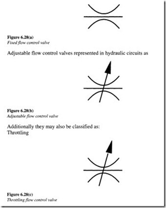
Fixed or non-adjustable flow control valves represented symbolically as m Figures 6.28(a)-(d).
Let us study in detail the common flow control valve types employed in hydraulic circuits from their operational, functional and application point of view.
Globe valve
This is the simplest form of a flow control valve. The globe valve gets its name from the disk element ‘globe’ that presses against the valve seat to close the valve.
A simplified view of a globe valve has been illustrated in Figure 6.29.
The fluid flow through the valve is at right angles to the direction of flow in pipes. When this valve is opened, the entire surface of the globe moves away from the valve seat at once. Due to this action, a globe valve provides an excellent means of throttling the flow. In a hydraulic system, the globe valve can be operated either manually by means of a hand wheel or mechanically by means of an actuator.
Butterfly valve
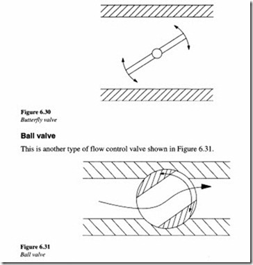
This is another type of flow control valve. It consists of a large disk which is rotated inside a pipe, the restriction in flow being determined by the angle. Figure 6.30 shows a simple design of a butterfly valve.
The advantage with this valve is that it can be constructed to almost any size. These valves are widely used for controlling gas flow. But a major problem associated with these valves is the high amount of leakage in the shut-off position.
It is made up of a ball with a through hole which is rotated inside a machined seat. The manner in which flow control is exercised can be understood better with the help of Figures 6.32(a) and (b).
From Figure 6.32(a), it can be seen how flow assists opening and opposes closing of the valve. Conversely, from Figure 6.32(b), the flow is seen to assist closing and oppose opening of the valve.
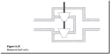
Figure 6.33 shows the balanced version of a ball valve. This valve uses two plugs and two seats with opposite flows resulting in very little dynamic reaction onto the actuator shaft, although at the expense of higher leakage.
Throttling only or non-pressure-compensated valve
This type of valve is used where the system pressures are relatively constant and the motoring speeds are not too critical. They work on the principle that the flow through an orifice will be constant if the pressure drop remains constant.
 The figure of a non-pressure-compensated valve shown in Figure 6.34 also includes a check valve which permits free flow in the direction opposite to the flow control direction. When the load on the actuator changes significantly, the system pressure changes. Thus, the flow rate through the non-pressure-compensated valve will change for the same flow rate setting.
Pressure-compensated flow control valves
Figure 6.35 illustrates the operation of a pressure-compensated valve. The design incorporates a hydrostat which maintains a constant 1.4 kg/cm2 (20 psi) pressure differential across the throttle which is an orifice, whose area can be adjusted by an external knob setting. The orifice area setting determines the flow rate to be controlled. The hydrostat is normally held open by a light spring. However, it starts to close as inlet pressure increases and overcomes the spring tension. This closes the opening through the hydrostat, thereby blocking all the flow in excess of the throttle setting. As a result, the only amount of fluid that can flow through the valve is that amount which a 1.4 kg/cm2 (20 psi) pressure can force through the throttle.
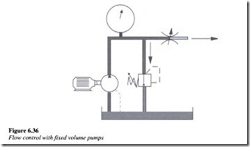
To understand better the concept of pressure compensation in flow control valves, let us try and distinguish between flow control in a fixed displacement pump and that in a pressure-compensated pump. Figure 6.36 is an example of flow control in a hydraulic circuit with fixed volume pumps.
In this system, a portion of the fluid is bypassed over the relief valve in order to reduce flow to the actuator. Pressure increases upstream as the flow control valve, which in this case is a needle valve, is closed. As the relief pressure is approached, the relief valve begins to open, bypassing a portion of the fluid to the tank.
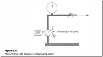
Flow control in a pressure-compensated pump as illustrated in Figure 6.37, is different in that the fluid is not passed over the relief valve. As the compensator setting pressure is approached, the pump begins the de-stroking operation, thereby reducing the outward flow.
The design of a pressure-compensated flow control valve is such that it makes allowances for variations in pressure, before or after the orifice. In a pressure-compensated flow control valve, the actuator speed does not vary with variation in load.
Meter-in and meter-out functions
Meter-in is a method by which a flow control valve is placed in a hydraulic circuit in such a manner that there is a restriction in the amount of fluid flowing to the actuator. Figure 6.38(a) shows a meter-in operation in a hydraulic system.
If the flow control valve were not to be located, the extension and retraction of the actuator which in this case is a cylinder, would have proceeded at an unrestricted rate. The presence of the flow control valve enables restriction in the fluid flow to the cylinder and thereby slowing down its extension. In the event of the flow direction being reversed, the check valve ensures that the return flow bypasses the flow control valve.
For the same meter-in operation, Figure 6.38(b) shows shifting of the flow control to the other line. This enables the actuator to extend at an unrestricted rate but conversely the flow to the actuator during the retracting operation can be restricted so that the operation takes place at a reduced rate. The meter-in operation is quite accurate with a positive load. But with an overrunning load over which the actuator has no control, the cylinder begins to cavitate.
