Flovvrneters
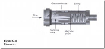
Flowmeters are used to measure flow in a hydraulic circuit. As shown in Figure 6.49, flowmeters mainly comprise of a metering cone and a magnetic piston along with a spring, for holding the magnetic piston in the no-flow position.
Flow meters are normally not bi-directional in nature. They in fact act as check valves and block flow in the reverse direction. Initially the fluid entering the device flows around the metering cone, exerting pressure on the magnetic piston and spring. With increase in flow in the system, the magnetic piston begins compressing the spring and thereby indicates the flow rate on a graduated scale.
Related posts:
Motors:Types of electric motors
Applications on pneumatic:Air gauging
Applications on pneumatic:Air springs
Applications on pneumatic:Mining and quarrying equipment.
BASIC DIAGRAMS AND SYSTEMS:FLUID POWER SYSTEMS
Moisture and condensation:Air processes and Condensation in reception hopper.
Operating problems:Vacuum nozzles and Flow control.
Conveying capability:High pressure conveying – Part III
HYDRAULIC PUMPS:Radial Piston Pumps
HYDRAULIC PUMPS:Vane Pumps
Air compressors, air treatment and pressure regulation.
Pascal's law.
Hydraulic Pumps and Pressure Regulation:Pump types
Air Compressors, Air Treatment and Pressure Regulation
FORCED CONVECTION:TURBULENT FLOW IN TUBES
