Compressor types
Like hydraulic pumps, air compressors can be split into positive displacement devices (where a fixed volume of air is delivered on each rotation of the compressor shaft) and dynamic devices such as centrifugal or axial blowers. The vast majority of air compressors are of the positive displacement type.
A compressor is selected by the pressure it is required to work at and the volume of gas it is required to deliver. As explained in the previous section, pressure in the receiver is generally higher than that required at the operating position, with local pressure regulation being used. Pressure at the compressor outlet (which for practical purposes will be the same as that in the receiver) is called the working pressure and is used to specify the compressor. Pressure at the operating point is called, not surprisingly, the operating pres sure and is used to specify valves, actuators and other operating devices.
Care should be taken in specifying the volume of gas a compressor is required to deliver. Expression 3.1 shows the volume of a given mass of gas to be highly dependent on pressure and temperature. Delivery volume of a compressor is defined in terms of gas at normal atmospheric conditions. Two standards known as standard temperature and pressures (STP) are commonly used, although differences between them are small for industrial users.
The technical normal condition is:
The term normal temperature and pressure (NTP) is also used.
Required delivery volume of a compressor (in M3 min-1 or ft3 min-1, according to the units used) may be calculated for the actuators at the various operating positions (with healthy safety margins to allow for leakage) but care must be taken to ensure this total volume is converted to STP condition before specifying the required compressor delivery volume.
A compressor delivery volume can be specified in terms of its theoretical volume (swept volume multiplied by rotational speed) or effective volume which includes losses. The ratio of these two volumes is the efficiency. Obviously the effective volume should be used in choosing a compressor (with, again, a safety margin for leakage). Required power of the motor driving the compressor is dependent on working pressure and delivery volume, and may be determined from expressions 2.2 and 2.5. Allowance must be made for the cyclic on/off operation of the compressor with the motor being sized for on load operation and not averaged over a period of time.
Piston compressors
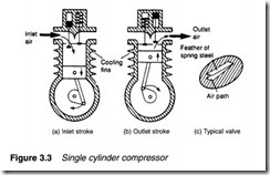
Piston compressors are by far the most common type of compressor, and a basic single cylinder form is shown in Figure 3.3. As the piston descends during the inlet stroke (Figure 3.3a), the inlet valve opens and air is drawn into the cylinder. As the piston passes the bottom of the stroke, the inlet valve closes and the exhaust valve opens allowing air to be expelled as the piston rises (Figure 3.3b)
Figure 3.3 implies that the valves are similar to valves in an internal combustion engine. In practice, spring-loaded valves are used, which open and close under the action of air pressure across them. One common type uses a ‘feather’ of spring steel which moves above the inlet or output port, as shown in Figure 3.3c.
A single cylinder compressor gives significant pressure pulses at the outlet port. This can be overcome to some extent by the use of a large receiver, but more often a multicylinder compressor is used. These are usually classified as vertical or
horizontal in-line arrangements and the more compact V, Y or W constructions.
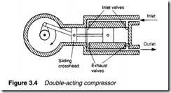
A compressor which produces one pulse of air per piston stoke (of which the example of Figure 3.3 is typical) is called a single acting compressor. A more even air supply can be obtained by the double acting action of the compressor in Figure 3.4, which uses two sets of valves and a crosshead to keep the piston rod square at all times. Double-acting compressors can be found in all configurations described earlier.
Piston compressors described so far go direct from atmospheric to required pressure in a single operation. This is known as a single stage compressor. The general gas law (expression 1.19) showed compression of a gas to be accompanied by a significant rise in gas temperature. If the exit pressure is above about 5 bar in a single acting compressor, the compressed air temperature can rise to over 200°C and the motor power needed to drive the compressor rises accordingly.
For pressures over a few bar it is far more economical to use a multistage compressor with cooling between stages. Figure 3.5 shows an example. As cooling (undertaken by a device called an intercooler) reduces the volume of the gas to be compressed at the second stage there is a large energy saving. Normally two stages are used for pneumatic pressures of 10 to 15 bar, but multistage compressors are available for pressures up to around 50 bar.
Multistage compressors can be manufactured with multicylinders as shown in Figure 3.5 or, more compactly, with a single cylinder and a double diameter piston as shown in Figure 3.6.
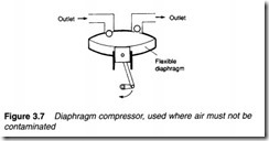
There is contact between pistons and air, in standard piston compressors, which may introduce small amounts of lubrication oil
from the piston walls into the air. This very small contamination may be undesirable in food and chemical industries. Figure 3.7 shows a common way of giving a totally clean supply by incorporating a flexible diaphragm between piston and air.
Screw compressors
Piston compressors are used where high pressures (> 20 bar) and relatively low volumes (< 10,000 m3 hc1) are needed, but are mechanically relatively complex with many moving parts. Many applications require only medium pressure (< 10 bar) and medium flows (around 10,000 m3 hc1). For these applications, rotary compressors have the advantage of simplicity, with fewer moving parts rotating at a constant speed, and a steady delivery of air without pressure pulses.
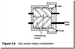
One rotary compressor, known as the dry rotary screw compressor, is shown in Figure 3.8 and consists of two intermeshing rotating screws with minimal (around 0.05 mm) clearance. As the
screws rotate, air is drawn into the housing, trapped between the screws and carried along to the discharge port, where it is delivered in a constant pulse-free stream.
Screws in this compressor can be synchronised by external timing gears. Alternatively one screw can be driven, the second screw rotated by contact with the drive screw. This approach requires oil lubrication to be sprayed into the inlet air to reduce friction between screws, and is consequently known as a wet rotary screw compressor. Wet screw construction though, obviously introduces oil contamination into the air which has to be removed by later oil separation units.
Rotary compressors
The vane compressor, shown in Figure 3.9 operates on similar principles to the hydraulic vane pump described in Chapter 2, although air compressors tend to be physically larger than hydraulic pumps. An unbalanced design is shown, balanced versions can also be constructed. Vanes can be forced out by springs or, more commonly, by centrifugal force.
A single stage vane compressor can deliver air at up to 3 bar, a much lower pressure than that available with a screw or piston compressor. A two-stage vane compressor with large low pressure and smaller high pressure sections linked by an intercooler allows pressures up to 10 bar to be obtained.
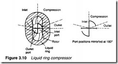
Figure 3.10 shows a variation on the vane compressor called a liquid ring compressor. The device uses many vanes rotating inside an eccentric housing and contains a liquid (usually water) which is flung out by centrifugal force to form a liquid ring which follows the contour of the housing to give a seal with no leakage and minimal friction. Rotational speed must be high (typically 3000 rpm) to create the ring. Delivery pressures are relatively low at around 5 bar.
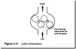
The lobe compressor of Figure 3.11 (often called a Roots blower) is often used when a positive displacement compressor is needed with high delivery volume but low pressure (typically 1-2 bar). Operating pressure is mainly limited by leakage between rotors and housing. To operate efficiently, clearances must be very small, and wear leads to a rapid fall in efficiency.
Dynamic compressors
A large volume of air (up to 5000 m3 min-1) is often required for applications such as pneumatic conveying (where powder is carried in an air stream), ventilation or where air itself is one component of a process (e.g. combustion air for gas/oil burners). Pressure in these applications is low (at most a few bar) and there is no need for a positive displacement compressor.
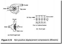
Large volume low pressure air is generally provided by dynamic compressors known as blowers. They can be subdivided into centrifugal or axial types, shown in Figure 3.12. Centrifugal blowers (Figure 3.12a) draw air in then fling it out by centrifugal force. A high shaft rotational speed is needed and the volume to input power ratio is lower than any other type of compressor.
An axial compressor comprises a set of rotating fan blades as shown in Figure 3.12b. These produce very large volumes of air, but at low pressure (less than one bar). They are primarily used for ventilation, combustion and process air.
Output pressures of both types of dynamic compressor can be lifted by multistage compressors with intercoolers be tween stages. Diffuser sections reduce air entry velocity to subsequent stages, thereby converting air kinetic energy to pressure energy.
Positive displacement compressors use oil to lubricate the close machined parts and to maintain the air seal. Dynamic compressors have no such need, and consequently deliver very clean air.

