SYSTEM MAINTENANCE
Maintenance requirements can be considered under three headings
• Tools and appliances.
• Systems.
• Compressors.
They are equally important, but require different maintenance intervals. The life of a pneumatic tool is likely to be lower than that of a compressor. Often a percussive tool, for example, will have a commercial life no longer than that of the contract on which it is intended to be used, perhaps a year or 18 months, whereas a compressor may survive for many years, passing from contract to contract. This is bound to be reflected in the attention that is given to planned maintenance. However if it is important that tools should operate with the minimum of trouble, the proper degree of maintenance must be established for each of them.
For underground drilling, where maintenance facilities are limited and where drilling performance in terms of overall cost per metre of drilled tunnel is a crucial factor in mining costs, the fitter responsible for ensuring that the tools are kept at peak performance is known as the “drill doctor”, which indicates the importance of his work.
Air tools
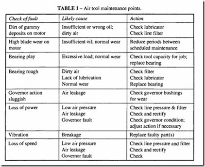
A programme for air tool maintenance should cover the following points:
• Ensuring that the air supply is maintained at the required pressure with the required delivery.
• Regular checking and refilling of lubricators to ensure adequate lubrication. This may require attention more than once per shift, so the operator should be supplied with equipment and lubricant for this purpose.
• Checking tools for damage.
• Checking that the tools are handled in a proper manner, that they are cleaned and lubricated after use.
• Checking that the proper tool bit or attachment is kept sharp and in good condition. The most common cause of early troubles with workshop tools is lack of lubrication.
The next is abuse, such as tools being dropped or dragged around by the hose, or generally
misused. The design of the work area itself and the allocation of racks for holding tools when not in use can be a form of preventive maintenance. The use of incorrectly sharpened tool bits in the case of a chipping hammer or drill, or a badly dressed wheel in the case of a grinder, can result in an unnecessarily severe reaction on the tool and a correspondingly heavy force having to be applied by the operator; these will reduce the life of the tool.
Scheduled maintenance should preferably be the main responsibility of a nominated individual or section, with the operator bearing his share of that responsibility; he must be aware of the necessity for proper lubrication and simple care of the tools in his charge. Records of each tool should be kept to ensure that they are withdrawn from service at regular intervals for stripping, inspection and replacement of worn or damaged parts. The manufacturer’s schedules of maintenance should be strictly adhered to, with a copy placed in every workshop. This applies to all kinds of tool. A record for each tool referenced against the operator will form a guide as to which individuals are responsible for the greater damage and misuse, or which operations are badly matched to the task they have to perform. In the case of major repairs, the tools may require to be returned to the manufacturer. With good preventive maintenance and efficient scheduled maintenance, a major break down is unlikely until the tool nears the end of its natural life. The value of a tool is represented by its initial cost less the amortisation rate, and if the major repair costs exceed the value of the tool, it would be better to replace it with a new one. This is particularly true of workshop tools.
Appliance maintenance
Overhaul of air-operated appliances requires the following precautions:
• All air pressures to be completely released from the system.
• It should be impossible to start the appliance inadvertently.
• The correct tools must be available.
• Adequate lifting gear should be available and checked to be in good condition. After maintenance and before clearing the machine for use, check:
• The operating pressures, speed and working temperature are correct.
• The controls and shut-down devices work correctly.
• That the sump or oil container is filled with the correct grade of oil, where appropriate.
• That there is a full flow of coolant, where appropriate.
• Condition of exhaust or discharge pipe and pulsation chamber. Clean off any deposits.
• Clean the outside of the appliance.
• Record the work done and replacement parts.
Air cylinder maintenance
Air cylinders require little in the way of maintenance if properly used, except for periodic replacement of expendable parts, such as seals, boots and gaiters. The items to be checked include piston seals, end cover seals, rod seals and bearings.
The servicing interval will depend on the frequency of operation, the total number of operations and the working conditions. Scraper rings and, in poor environmental conditions, external gaiters together with adequate lubrication can protect the inside of the cylinder against abrasive atmospheric contaminants; the lubricant must be resistant to water washing. Modern cylinders are pre-coated during assembly with a lubricating compound which adheres to the surface for a considerable time. This helps to extend the servicing period but should not be used as an excuse not to supply lubricant in the air.
Seal wear and seal life depend very largely on the condition of the bore and the rod. Corrosion, pitting, abrasion or damage to these surfaces can result in high seal wear and premature failure. Intermittent use, with long periods of idleness during which the seals may dry out is also damaging. Most seal failures can be traced to bad initial fitting, the wrong type of seal or the wrong material specification.
Piston seal leak is not always easy to detect, since the first evidence may appear as leakage past the exhaust ports of the control valve, when a valve seal, ratherthan a piston seal may be suspect. A simple check is to disconnect the exhaust lines from the cylinder to the valve. If there is leakage through that line, the piston seals are faulty; if there is no leakage, the valve is probably faulty.
Tie rod construction makes cylinder disassembly easy. A point to watch with spring return cylinders is that one end cover will be under spring load and will require careful backing off until the spring pressure is relieved. On long stroke spring return cylinders, it may be advantageous to extend the lengths of the side rods to accommodate the full uncompressed length of the spring with the cover still on the side rods.
Replacement of the piston seals may not require disassembly of the piston, depending on the type of seal fitted, and the manner in which they are retained. Precautions should be taken when refitting seals to make sure that the correct tools are used to avoid stretching, nicking or otherwise damaging them. Always replace static end seals with new ones when they are disturbed. A thorough lubrication of the internal surfaces of the cylinder and the static seals is to be recommended.
System maintenance
Scheduled periods for the inspection of drains, moisture traps and separators should be based on experience with the components and the environmental conditions and the efficiency and type of compressor. Manufacturers recommendations should be used as an initial guide.
Filters and filter separators at individual tool stations must receive regular attention, particularly if they are of the manual drain type. Where practicable the automatic or semi automatic type should be installed; the semi-automatic drain operates when the air supply is removed. The level of contaminants will normally be visible in the filter bowl if it is a transparent polycarbonate type or in a sight glass if of metal construction.
A tell-tale operated by pressure drop through the filter operates when the contaminant level is excessive, but it should be drained well before that.
All types should be cleaned or replaced in accordance with the manufacturer’s instructions. Some can be cleaned by blowing through, others need replacement elements. If a filter should be damaged during servicing it must be replaced. Note that filter bowls
made of polycarbonate should only be washed in warm water with a detergent, not with a solvent.
Clogged filters are the most common reason for pressure drop at the point of use. Air leaks or constrictions in the flexible lines are less obvious causes of pressure drop; the former can usually be heard, with the tool connected but switched off. Kinks or damage that has not produced puncturing show in the form of variable performance as the tool position is changed.
Less obvious sources of pressure drop may occur further back in the system. With adequate line-sizing and all connections in good condition, the pressure drop between receiver and tool station should not exceed 0.4 bar. Additional losses at the tool itself should not exceed a further 0.4 bar. About I0% of the system pressure is acceptable as an overall pressure loss.
Regardless of the pressure loss as installed and originally worked, any further loss noticed is a cause for concern and should be immediately attended to. Do not increase the setting of the regulator pressure to compensate for the pressure loss, otherwise when the system faults are corrected, thepressure may be too high. Loss of pressure not only reduces the tool working efficiency, but may be expensive in terms of air wastage if due to a leak. Leakage may develop at joints, at hose connections or in traps where the valve has been jammed open by contaminants. Excessive line pressure can be as bad as lack of line pressure. The latter reduces the working efficiency of the tool, often proportionally more than just by the pressure reduction, while the former can result in accelerated wear and over-stressing of parts, with no increase in performance.
Lubricators at tool stations need regular attention to ensure that an adequate supply of oil is maintained. Only the specified oil should be used, not only because an oil of different viscosity may affect the lubrication rate, but also because an unapproved oil may not have the qualities necessary for a tool lubricant. Refer to the chapter on Lubricants.
Pipe work should require minimum attention, usually only inspection for possible leaks.
Installation faults needing correction are:
• Sagging or displaced pipes requiring proper support.
• Evidence of whipping at bends or vibration due to inadequate support during pressure surges.
• Distortion of runs caused by expansion or contraction movement, which can be cured by incorporating bends or expansion joints.
Compressor maintenance
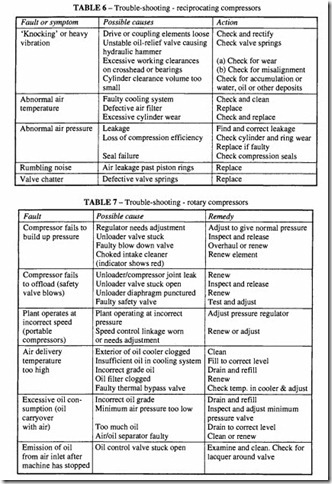
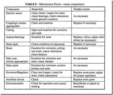
While a general indication can be given of the principles of compressor maintenance (see Tables 4 to 8), it is better to rely on the manufacturer’s schedules where available. Basic requirements include:
• cleanliness (regular cleaning of intake filters);
• attention to drain points on the compressor, intercooler and receiver;
• ensuring an adequate supply of lubricant;
• correct tensioning of intercooler and main driving belts;
• routine oil changes in accordance with the manufacturer’s recommendations;
• cleaning or replacement of intake filters;
• inspection and cleaning of valves on a reciprocating compressor;
• inspection and replacement of vanes on a rotary vane compressor.
Compressor manufacturers normally specify comprehensive maintenance requirements and run courses for skilled personnel responsible for that work. They will also issue recommended lists of spares to be carried and have service kits available with installation instructions. It is always advisable to buy approved components from the same source as the original purchase.


