Contractors tools
The designation “Contractors Tools” refers to compressed air equipment used on construction and building sites. There is a degree of common usage between the three broad site classifications – industrial, contractors and mining. Thus chipping hammers may be used for metal dressing in a factory and for concrete dressing on a construction site. The needs of the miner and the construction site worker are also similar; a rock drill can be used for drilling rock on a road construction contract and for quarrying and mining. So the distinctions made here are somewhat arbitrary.
Road breakers
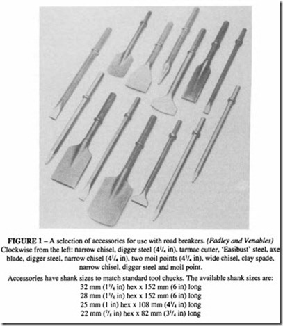
A common contractor’s tool is the road breaker, paving breaker or concrete breaker. This is sometimes referred to as a road drill, but this is an incorrect usage; the term “drill” is restricted to those tools which either incorporate rotation as part of their mechanism or are separately and externally rotated. A road breaker has no rotation; it is a tool specifically designed to produce a heavy blow to break up road surfaces, and to perform similar allied functions. With the addition of various tool bits and chisels, it can also act as a clay spader, tie tamper, post-hole driver, back-fill rammer and pile driver. See Figure I.
Modern road breakers are designed with a degree of exhaust muffling to reduce the possibility of noise damage to the operator. Some tools are available in both standard and muffled form, although it is unlikely that the standard form would be able to meet the EC limits for maximum noise level. The standard form may only be sold in those countries outside the European Union where noise regulations do not apply. Some modem tools are designed in such a way that they may only be used in the muffled form- the muffler forms an integral part of the construction which, if removed, would render the tool unusable. A number of manufacturers make tools of this kind. This has the advantage from environ mental considerations that the tool may only be operated in the muffled condition.
Most mufflers make use of rigid polyurethane, a material which has demonstrated its ability to withstand the rough usage of a construction site. It can be moulded without expensive equipment, so it can be economically made up in small batches. It is available in a variety of colours.
Figure 2 shows a modern road breaker. It has many features common to other percussive
tools such as picks and spaders which incorporate a distribution valve. The method of operation is as follows:
Air is admitted through the main swivel connection. When the trigger is depressed, the ball valve opens admitting air to the distribution valve situated at the top of the piston. The valve in this example is a simple plate valve, although more complex shapes are also found. It is held on its top or bottom seat by differential pressures on the upper and lower surface: when the valve is on its bottom seat, air is directed to the under surface of the piston; when the valve is on its top seat, air passes to the top of the piston. When air is first admitted to the tool, both piston and valve are at their down position, so air passes into the bottom chamber of the cylinder forcing the piston up. Towards the end of its upwards travel, the piston compresses the air in the upper cylinder, which causes the valve to move on to the
The components are held together by long side belts (not shown). Incorporated in the handle is an oil reservoir. (CompAir Holman) opposite seat. At the same time the air in the bottom chamber exhausts to atmosphere via the passages in the muffler. The air then acts on the top of the piston forcing it down. When the piston impacts the anvil block, its energy passes into the chisel and then into the concrete to be broken. The air exhausts from the upper cylinder and the fall in pressure allows the valve to move once more onto its bottom seat. The cycle then repeats at a frequency, of the order of 1000 to 1500 rev/min, depending on the design and the air pressure.
The shank of the chisel is of hexagonal cross-section; the latch-type retainer keeps the chisel held in the front head by the collar on the chisel shank; round shanks are also found in picks where it is not required to turn the tool. A variety of different retainers are made: a latch type is illustrated and is the most common, but screw and spring types are also supplied.
Most tools incorporate an oil reservoir which dispenses a small amount of oil into the working parts of the tool each time the trigger is pressed. It is important to keep this reservoir topped up at least once during each shift, but this form of lubrication is not as
satisfactory as a separate lubricator inserted in the air line. The use of a specially formulated oil is recommended for this tool.
This tool also incorporates a vibration suppression device, which can be seen on the handles. The handles can pivot on a pair of pins and the anti-vibration element consists of a lateral spring and a rubber cushion. There is an increasing demand for some form of cushioning to meet health and safety requirements.
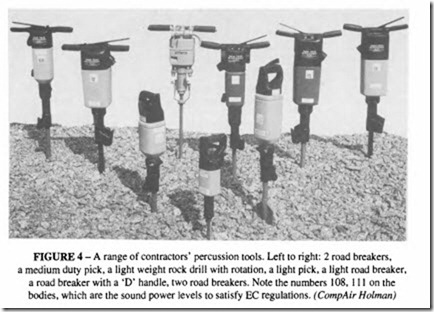
A range of contractors’ percussive tools is shown in Figure 4.
Rock drills
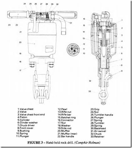
Figure 3 is a cross-section of a typical modern hand-held rock drill, also illustrated in Figure 4. Superficially it has many similarities to the road breaker discussed above, but
there are some major differences. It has the same type of disc valve and the cycle of operations is similar except that, in addition to the reciprocation of the piston, the drill bit is rotated by an internal ratchet mechanism. The piston has an internally rifled bush which matches a similarly rifled bar held in the backhead of the drill; a ratchet mechanism ensures that the piston rotates only on the upward (or return) stroke. On the power (ie the down) stroke there is no resistance to the motion of the piston, so that the full pressure is available to produce impact energy. On the return stroke, the piston rotates along the rifling and transfers that rotation to the drill steel by means of straight splines on the trunk of the piston which mesh with similar splines on the chuck.
A rock drill of this kind incorporates a means for flushing out the drilled hole, which can be done either by air or water. Air flushing is either continuous, when air passes directly from the exhaust port or is under operator control by selection of the blowing position on the tumbler handle. In the latter alternative the full flow of the air passes down through the hole in the drill steel to give full pressure clearance. Water flushing, which is necessary underground where the dust has to be suppressed, is achieved by passing water from a separate connection on the backhead down a tube passing through the piston into the drill steel. The water pressure has to be kept at a minimum of about I bar.
This particular drill is capable of drilling a 45 mm diameter hole at a penetration speed of 180 mm/min in granite; in limestone and softer rocks, the drilling speed can be up to twice as much.
A rock drill has to stand much harder usage than a breaker. The blow frequency is higher and the level of energy is higher. The extra complication of the rotation mechanism underlines the need for good lubrication at all times, so a separate line oiler should be included in the airline feeding the drill, even though some manufacturers offer a drill with an oil reservoir in the handle for occasional use. The consumption of spare parts is high, particularly of such items as the chuck, the rotation ratchet and the rifle nut. Typically during the life of a drill, it will consume two to three times its first cost in spare parts.
One distinction between a drill and a breaker is the magnitude of the energy in each blow and the shape of the cylinder to produce that energy. A breaker has a long stroke and smaller bore, typically about 45 mm bore with 150 mm stroke, producing a heavy-hitting low-frequency blow. The hand-held rock drill described above has a 64 mm bore and a 48 mmstroke. Theenergycontentoftheindividual blow is not so important as the total energy per minute, so the drill maximises that energy by increasing the frequency of operation. Rock drills of this general type incorporating rifle-bar rotation can be as small as a miniature drill weighing 2 to 3kg, consuming 121/s of air, up to the large rig-mounted drills weighing 150kg and consuming 240 1/s. Even larger drills, with independent rotation (the rotation is achieved with a separate motor directly connected to the drill chuck) are available, weighing 300 kg, consuming 300 1/s. Drills heavier than 30 kg are not suitable for hand use.
Performance estimation of percussive tools
Estimating the performance of percussive tools is not a particularly easy exercise, when compared with their hydraulic or pneumatic counterparts. The difficulty stems partly from an uncertainty about theamountofexpansionoftheairat thepointofuse.Modern methods of analysis rely on computer simulation, for which specialist programs are available. A description of these methods is outside the scope of this volume and the interested reader is referred to one of the companies specialising in simulation techniques.
The “broad brush” method of analysis adopted here makes it possible to compare the performance of one tool with another, and enables the influence of the main tool parameters, such as bore, stroke and air pressure to be studied.
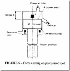
Figure 5 shows the forces acting on the piston of a percussive tool. The following quantities are derived from a consideration of the acceleration of the piston.
These equations give only an indication of the behaviour of a tool and as such are useful for estimating what is likely to be the result of changing the pressure or the dimensions of an existing tool. They are less useful when attempting to predict the performance of a tool off the drawing board. For such purposes, a more complex simulation, involving a computer analysis is required.
When considering the above expressions note that the pressure Pis the mean effective pressure on the power stroke, which will generally be lower than the applied pressure at the inlet. Furthermore the mean pressure on the return stroke will be lower than that on the power stroke. The factor by which the inlet pressure is to be multiplied to get the effective pressure depends on the detail design of the tool, particularly that of the distributor valve. P on the power stroke will be about 0.6 times the inlet pressure and P on the return stroke will be about 0.4 times the inlet pressure. The return pressure and the area below the piston on which it acts will govern the value of k. Typically k will be 2.0 to 2.5.
The air consumption of a tool of this kind is theoretically equal to the total swept volume of the power and return stroke per second of the compressed air. In terms of the usual FAD (free air delivered), the pressure ratio must be taken into account.
This expression should be used with reservation. It takes no account of leakage and other wastage, which is inevitable because there are no seals on the piston. In practice the actual air consumption may be as much as 50% in excess of the calculated value.
Another expression may sometimes be useful. This concerns the external reaction force on the handle or on the support structure of a rig-mounted drill. It is a measure of the force that must be applied by the operator to use the power generated by the tool.
If the tool is held vertically, as for example the case of a road breaker, the operator applies the difference between this and the dead weight of the tool. Over a sustained period an operator cannot apply more than 100 N, and for short periods more than his body weight. It is this reaction force more than any other factor which limits the usable power of a hand held tool. If a tool were designed with a greater potential power, the operator would find it impossible to handle.
The reaction force calculated here is the mean static force. There is in addition a vibratory element, which varies with the tool design. Apart from vibration induced white fingers, a disease of tool operators, the presence of vibration at the tool handle represents a fatigue-inducing factor which may be more limiting than the static force.
Rotation systems
Another aspect of percussive tool behaviour, capable of theoretical estimation, is the torque produced by a rifle-bar rotation mechanism.
The function of this method of rotation should be understood first. The modem rock drill derives its action from the traditional method of hand drilling with hammer and chisel. The old time miners used to drill in teams: two men would wield hammers, and a third would hold the chisel and rotate it. The rock was broken by chisel action rather than by rotary cutting, and so it is in a modern rock drill; only in relatively soft rock such as coal and shale is it possible to drill by rotary action. It is easier to rotate a drill by hand in an anti-clockwise direction, so that is the direction that a drill turns. Smaller drills that can be used for both rotary and impact drilling are also fitted with clockwise rotation; and the heavier rock drills, using coupled rods that have to be screwed together, include a facility for reversing the direction of rotation to allow for uncoupling of the rods. Some stoper drills, which serve the dual purpose of drilling and acting as torque wrench for roof bolting, are also equipped with a clockwise rotation mechanism.
A rock drill must be forced against the rock by a feed force having the magnitude given in the equation above. The applied force should be just sufficient to keep the bit in contact with the rock, but no more. As the bit rebounds after the rock is broken, there is no resistance to rotation, and so a comparatively small torque is needed just to index the bit to the next cutting position. Air or water removes the chippings so that the chisel action is not cushioned by drilling detritus.
It is for this reason that the rotation occurs on the return stroke of the piston. The angle of the splines on the rifling is just sufficient to index the bit by about 20 to 30 degrees per blow, so that while the blow frequency may be of the order of 2000 per minute, the rotational speed will be about I 00 per minute. It is usual in English usage to refer to a drill having a rotation (for example) of I in 30, as meaning that the bit rotates by one complete turn for every 30 inches of travel of the piston- a lead of 30 inches. Common values of lead are 30, 35, and 40. In SI units, the lead can be expressed in mm.
The shallowness of the angle of the rifle-bar, used to achieve such a slow rotation, means that friction between the splines and the rifle nut and between the chuck and the piston absorbs a high proportion of the available energy on the return stroke. It is important that the sliding parts are well lubricated to minimise the coefficient of friction and to prevent a common cause of wear- the break-up of the splined surfaces.
An advantage of this form of rotation is the absence of any appreciable reaction torque to be sustained by the operator.
Estimation of the torque provided by rifle bar rotation Refer to Figure 3. The relationship between rotational torque and force on the piston is as follows:
This formula is correct for consistent units.
The force F is the product of the area of the piston Ar (Figure 5) and the air pressure P,. This formula is accurate for consistent units.
As an example of the use of this formula, take a drill with a bore diameter of 66.7 mm in which dt = 19.3 mm, dz= 34mm, r=0.762 m (30 in). Two values of the coefficient of friction can be taken, Jl = 0 and 0.2.
A value of Jl = 0.2 is fairly typical for lubricated steel surfaces. It may be a little less between the steel rifle bar and the bronze rifle nut.
The return area, Ar, of the chosen dri II is 2303 mm 2 • The maximum operating pressure of the drill can be taken as 6 bar; whilst this pressure is not realised in the return chamber of the drill during normal operation, it is approached under stall conditions (when the calculation is likely to be of most use).
So the stall torque when Jl = 0 is given by:
The latter figure has been demonstrated to be experimentally correct for the chosen drill. The calculated values indicate two important points: the importance of reducing friction by supplying adequate and correct lubrication, and the torque available for rotating the drill is comparatively small. Should this value be applied, it will stop the operation of the drill. This can easily occur if the drill bit is allowed to jam in the hole through an accumulation of drilling debris. This is the main reason why, in most modern heavy rig mounted drills, the rotation mechanism is provided independently of the impact mecha nism by a separate motor able to supply much greater torque.
Drilling performance of a percussive rock drill
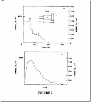
Figure 6 illustrates the principle of rock drilling. When the piston impacts the end of the drill stem, its kinetic energy is transformed into elastic energy which then passes down the rods as a stress wave until the interface between the bit and the rock is met, whereupon the
rock fractures. The shape of the stress wave (ie the plot of stress magnitude versus time) is an important element in assessing the effectiveness of the drill in breaking rock. The shape can be calculated from considerations of the geometry of the piston and the impact train of drill rod and bit. Its overall magnitude is proportional to the velocity of the piston. ‘fhe actual calculation of the stress pattern is a complex and time-consuming exercise, which is conveniently solved by a graphical method as described for example in “Down the-hole drilling using elevated air pressures”, M.G. Adamson, Quarry Managers’ Journal .A ugust 1967. Computer programs are also available to perform the same calculation (“Digital machine computations of the stress waves produced by striker impact in percussive drilling machines”, R. Simon, Rock Mechanics, ed. by C. Fairhurst, Pergamon Press).
Figure 7 compares a theoretical calculation with the actual stress pattern measured by a strain gauge.
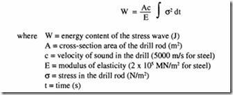
The total energy of the stress wave is given by:
The energy content of the wave can be used to assess the penetration rate of the drill, but it is difficult to relate directly the value ofW to the drilling speed, because of the variability of different rocks. Although a number of attempts have been made to define a property of a rock which allows a calculation of its “drillability”, none has been entirely successful. There is no substitute for drilling trials in the actual rock.
The stress pattern in the drill stem can also be used to assess the maximum stress that occurs in the elements of the impact train. Most modern drills are limited to an impact velocity of 10 m/s.
The initial stress caused by impact is given by
A stress level of this magnitude will be recognised as a very high one for repeated applications and calls for a good quality steel.
A number of specialist manufacturers make drill rods and screwed couplings. A wide variety of different types of thread and couplings are available, the choice is very wide and reference should be made to the manufacturer for recommendations.
Most modern drill bits use a tungsten carbide insert, which can adopt several different forms:
• for small diameter holes a single chisel bit;
• for larger diameter holes a cross or X-shaped bit;
• for the largest sizes, button bits.
Button bits have come into widespread use in recent years, mainly because they require little or no dressing to retain their drilling efficiency, whereas chisel bits require regular sharpening.
