AIR RESERVOIR (RECEIVER)
Air receivers, being simple volume tanks, are not often thought of as highly engineered items, but the use of simple engineering with receivers can reduce equipment costs. A pertinent example not uncommon in industry is the intermittent requirement for a fairly large volume of air at moderate pressure for a short period of time. Some boiler soot-blowing systems are in this class. The analysis necessary to arrive at the most economical equipment often involves the storage of air at high pressure to sup plement the compressor’s output when the demand requires. The following example is somewhat extreme, but emphasizes the need for proper receiver selection.
SIZING A RECEIVER TANK
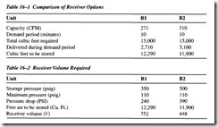
This application requires 1,500 cubic feet per minute (cfm) of free air at 90 pounds per square inch-gauge (psig) for 10 minutes each hour. This cycle of 10 minutes at 1,500 cfm and 50 minutes with zero demand repeats hourly. Alternatives obviously are possi ble: (A) install a 100-psig compressor and standard accessories large enough for the maximum demand requirements; or (B) install a smaller compressor, but for a higher pressure, and store the air in receivers during the off or no-demand period. At least two storage pressures should be considered. In all cases commercial compressor sizes are to be used. For (B1) assume 350 psig and for (B2), 500 psig. (See Table 16-1.)
The 100 psig machine for at least 1,500 cfm output, unit (A) has 1,660 cfm actual capacity and requires 309 brake horsepower (bhp) at full load. The minimum capacity for units B 1 and B2 must be calculated, since these can be compressing the full 60 minutes each hour..
Compressor (B1), for 350-psig discharge, is found to have a capacity of 271 cfm and a required brake horsepower of 85. Compressor (B2), for 500 psig, is found to be a standard size with a capacity of 310 cfm and requires 112 bhp. All selections provide some extra capacity for emergency and losses are economical two-stage designs.
Air compressed to 100 psig, to be used at 90 psig, provides no possibility of storage. Storage is practical at the other pressures selected. Compressor units B and C will operate at full load at their rated or lower pressures. Since the receiver pressure will fall during the 10 minutes when air is used faster than the compressor can replenish it, the unit will be operating at full capacity and will supply some of the demand. The full demand need not be stored.
The cubic feet of air to be stored represents the free air, at 14.7 psia, that must be packaged into the receiver above the minimum pressure required by the demand. In this case, the demand pressure is 90 psig, but an allowance for line losses and the nec essary reducing valve pressure drop would prevent the use of any air stored below 110 psig. The receiver has a volume of (V) expressed in cubic feet.
Pressure drop
This receiver volume may be in one or several tanks, the most economical number being chosen (see Table 16-2).
The final selection can be made only after consideration of the first cost of the compres sor, motor, starter, aftercooler, and receiver. The cost of installation, including founda tions, piping, and wiring, as well as the operating power cost, must also be considered. Inthe example, Table 16-3 provides a basic comparison of the three options.
Not all problems of this nature will result in the selection of the intermediate storage pressure. Although few will favor the 100-psig level, many will be more economical at the 500-psig level. Experience indicates that there is seldom any gain in using a higher storage pressure than 500 psig, since larger receivers become very expensive above this level and power cost increases.
Air reservoirs are classified as pressure vessels and have to conform to the ASME Pressure Vessel Codes. As such, the following attachments must be fitted:
• Safety valves
• Pressure gauges
• Isolation valves
• Manhole or inspection ports
• Fusible plug
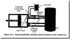
Air reservoirs are designed to receive and store pressurized air. Pressure regulating devices are installed to maintain the pressure within operational limits. When the air reservoir is pressurized to the maximum pressure set point, the pressure regulator causes the air com pressor to offload compression by initiating an electrical solenoid valve to use lubricating oil to hydraulically hold open the low-pressure suction valve on the compressor.
As the compressed air is used, the pressure drops in the reservoir until the low pressure set point is reached. At this point, the pressure-regulated solenoid valve is de-energized. This causes the hydraulic force to drop off on the low-pressure suction valve, restoring it to the full compression cycle.
This cycling process causes drastic variations in noise levels. These noises should not be regarded as problems, unless accompanied by severe knocking or squealing noises. Figure 16-1 shows a typical hydraulic unloader and its location on the compressor.


