DRY AIR DISTRIBUTION SYSTEM
Most plants are highly dependent on their compressed air supply, and it should be ensured that the air is in at least reasonable condition at all times, even if the drying sys-
Gas Outlet
tern is out of use for maintenance or repair. It is possible that the line condensation would be so bad that some air applications would be handicapped or even shut down if there were no protection. A vital part of all the effort to separate water in the conven tional compressed air system is also the trapping of dirt, pipe scale, and other contami nants. This is still necessary with a dried air system. As a minimum, all branch lines should be taken off the top of the main and all feeder lines off the top of branch lines.
Absolute prevention of line freezing can be obtained only when the dew point of the line air is below any temperature to which it may be exposed. Freezing is always pos sible if there is line condensation. For example, when air lines are run outdoors in winter weather or pass through cold storage rooms, the ambient temperatures will change the dew point and cause any moisture in the air to condense and freeze.
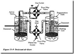
The dryer unit has an air inlet, an air outlet, a waste air outlet, two heater coils, and two four-way reversing valves (see Figure 15-9). Although the illustration shows the two tanks in a functioning mode, they are universal in operation. By this, we mean that this changes the tanks over when the active tank becomes totally saturated, and the tank that was on the regeneration cycle then becomes the active unit.
With this process, there will always be one tank in active service, and one on regener ation or stand-by. A timer governs the changeover process. The timer changes the position of the four-way, or reversing, valves. This operation reverses the airflow through the tanks; the tank that was regenerated will now dry the air, while the satu rated tank will be regenerated.
