PISTON Roo COLUMN STRENGTH
Long, slim piston rods may buckle if subjected to too heavy a push load. Table 6-1 sug gests the minimum diameter piston rod to use under various conditions of load and unsup ported rod length. It should be used in accordance with the instructions in the following paragraph. There must be no side load or bending stress at any point along the piston rod.
Exposed rod length is shown along the top of the table. This is usually somewhat longer than the actual stroke of the cylinder. The vertical scale (column I) shows the load on the cylinder and is expressed in English tons, i.e., 1 ton equals 2,000 pounds. If both the end of the rod and the front end of the cylinder barrel are rigidly supported, a smaller rod may have sufficient column strength, and you may use an exposed length of piston rod that is one-half of the actual total rod length. For example, if the actual rod length is 80 inches, and if the cylinder barrel and rod end are supported as described, you could enter the table in the column marked 40. On the other hand, if hinge mounting is used on both cylinder and rod, you may not be safe in using actual exposed rod length. Instead, you should use about twice the actual rod length. For example, if the actual rod length is 20 inches, you should enter the table in the 40-inch column.
When mounted horizontally or at any angle other than vertical, hinge-mounted cylin- ders create a bending stress on the rod when extended. In part, this bending stress is created by the cylinder’s weight. On large-bore and/or long-stroke hinge-mounted cylinders, a trunnion mount should be used in instead of tang or clevis mounts. In addition, the trunnion should be positioned so that the cylinder’s weight is balance when the rod is fully extended.
HYDRAULIC CYLINDER FORCES
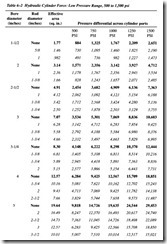
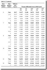
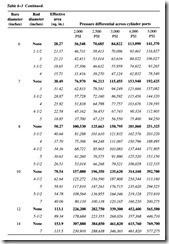
Tables 6-2 and 6-3 provide the mechanical forces, both extension and retraction, that can be generated by hydraulic cylinders. The tables are divided into the two principal operating pressure ranges associated with hydraulic applications.
Values in bold type show the extension forces, using the full piston area. Values in italic type are for the retraction force for various piston rod diameters. Remember that force values are theoretical, derived by calculation. Experience has shown that proba bly 5 percent but certainly no more than 10 percent additional pressure will be required to make up cylinder losses.
For pressures not shown, the effective piston areas in the third column can be used as power factors. Multiply effective area times pressure to obtain cylinder force pro duced. Values in two or more columns can be added for a pressure not listed, or force values can be obtained by interpolating between the next higher and the next lower pressure columns.
Pressure values along the top of each table are differential pressures across the two cylinder ports. This is the pressure to just balance the load and not the pressure that must be produced by the system pump. There will be circuit flow losses in pressure and return lines due to oil flow, and these will require additional pressure. When designing a system, be sure to allow sufficient pump pressure, about 25 to 30 percent, both to supply the cylinder and to satisfy system flow losses.
CYLINDER MOUNTING
Various cylinder mountings (Figure 6-8) provide flexibility in anchoring the cylinder. Rod ends are usually threaded for attachment directly to the load or to accept a clevis, yoke, or similar coupling device.
Foot and Centerline Lug Mounts
This type of mounting provides rigid attachment of the cylinder to a stationary, struc tural member of a machine. It also provides a firm foundation that equally transmits the forces generated by the hydraulic system, through the cylinder, to the movable machine component. Because of the rigid mount, this configuration provides the best transmission of force without induced sideload on the cylinder rod.
Front Flange Mount
As in the lug mount, the flange-mounted unit provides reasonably rigid attachment of the cylinder to a structural component of the machine. Because of the relatively small mounting area and absence of a rear mount, this configuration does not provide the full support of the lug mount design. As a result, care must be taken to minimize side load or overextension of the cylinder rod.


